My main idea consisted of two parts: first, create a minimum curvature trajectory and then develop a velocity profile based around it. This method is generally used by almost every paper written on this topic, at least as a starting point. I also calculated the velocity profile of the shortest path around the given track to show how bad the lap times are for it compared to the min curvature one. I also validated most of my results with data and literature I found online.
For this section, I followed a global approach for both the shortest path and min curvature trajectory. The methodology I stuck to is outlined in this paper, Race Driver Model.
I converted this entire subject into a quadratic programming (QP) problem and solved it with the help of the 'quadprog' function in MATLAB. I also derived the equations for H and B matrices myself in terms of the coordinates of the track edges. Then I substituted these matrices in the QP solver along with the constraints that restrict the trajectory within the boundaries. I also added another condition that requires the starting point to be the same as the end one. The reasoning behind this was to create a loop rather than a broken track at the end.
As soon as the solver is executed, it automatically outputs the results, making the solving time almost negligible. It usually takes around 11-12 iterations to find the result. Unfortunately, quadprog doesn't have the functionality to output the result of every iteration, making me incapable of rendering the really cool animated GIFs.
Some of the drawbacks and improvements to my method have been mentioned in this paper Minimum curvature trajectory planning and control for an autonomous race car. One critical simplifying assumption I made was neglecting the 2x'y' term in my curvature definition. This leads to a slightly suboptimal solution but significantly reduces the effort for calculating the H and B matrices. One improvement would be to use an iterative QP routine that replaces the reference line with the solution of the previous QP iteration.
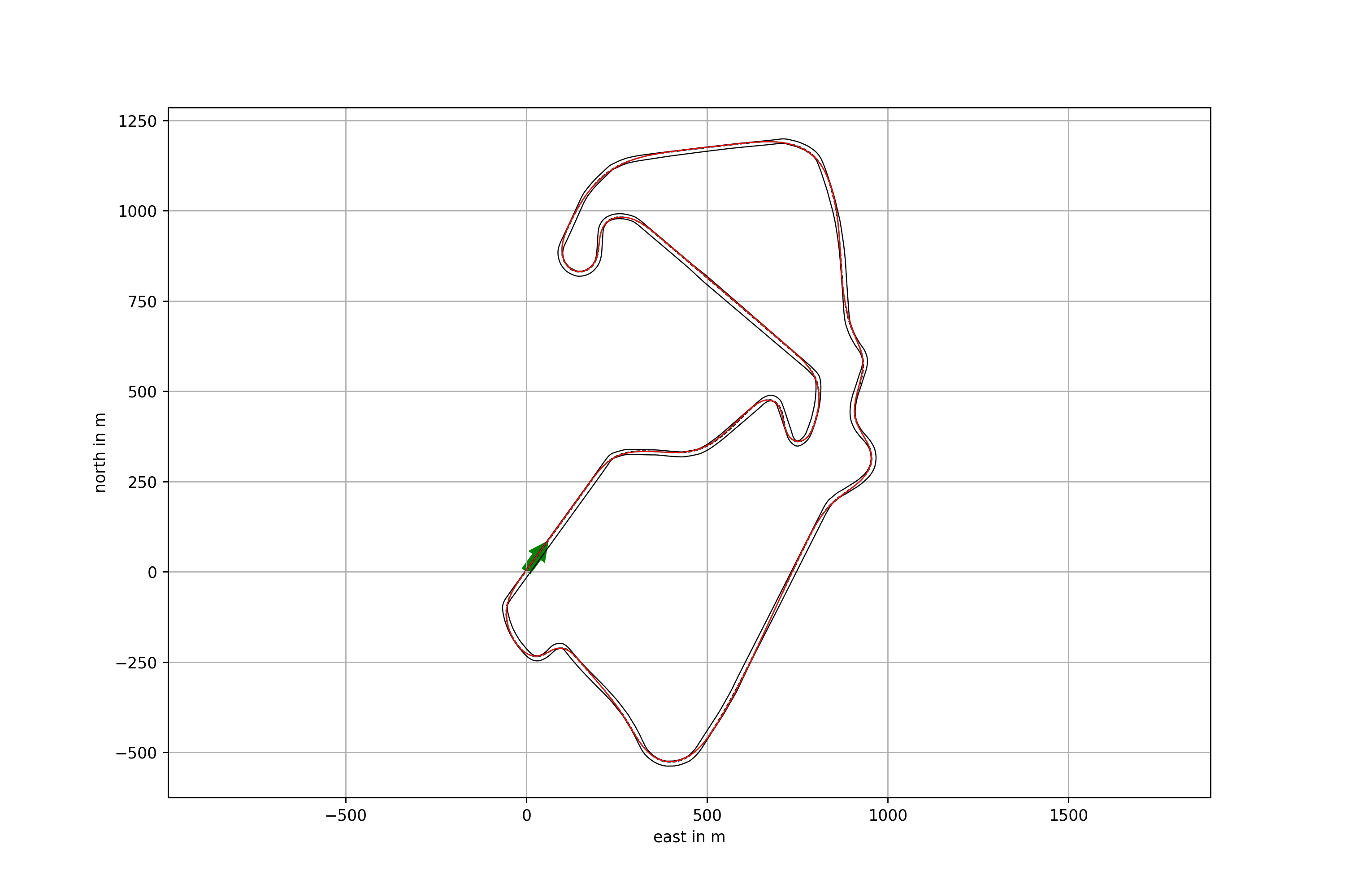
| Shortest Path Trajectory | Minimum Curvature Trajectory |
|---|---|
 |
 |
For comparison - Raceline uploaded by TUMFTM for Silverstone track
To generate a velocity profile, I referred to this paper, Optimized Trajectory Generation for Car-Like Robots on a Closed-Loop Track. Along with that, I also followed Optimal velocity profile generation for given acceleration limits: theoretical analysis, which actually inspired the previous report and mentioned it as a reference.
The main idea was to identify the max curvature points for the optimized trajectory, assign a certain critical velocity to each one, and generate velocity profiles around these points. Since it is assumed that the vehicle follows the course perfectly, the only driver input would be the throttle and brake commands. It is mentioned in the previous papers that to achieve minimum time, control inputs for acc and dec must be 1 and -1, respectively.
These intermediate velocity profiles are generated according to specific rules defined in the literature. The final profile is the minimum of all these in-between profiles. One modification that I made to these rules was to check if the critical velocity at the max curvature point was greater than the acc profile from the previous step; if it was, I continued the previous profile rather than starting a new one. The exact process was followed for the deceleration profiles.
Finally, lap times were calculated from the velocity and length vectors in order to validate my results with actual data.
| Track Name | Calculated (s) | Current Lap Record (s) |
|---|---|---|
| Silverstone, UK (F1) | 96.6 | 90 |
| Spa, Belgium (F1) | 109 | 106 |
As it was previously discussed, the literature mentioned in this section has some errors in the critical velocity and velocity iteration formulae. I have corrected them in my implementation. I have also included aerodynamics effects for traction and braking by inserting a -v^2 term within the equations. Since the velocities are really high in F1, aerodynamics drag cannot be neglected.
| Velocity Profile of Silverstone track | Velocity Track Map of Silverstone track |
|---|---|
 |
 |

This Simulink model extends the previous point mass model into a 3DOF one using the Stanley control methodology and various pre-built blocks in Simulink (MATLAB R2021b version). This model was built in collaboration with Veer Alakshendra, the author and mentor of this project. While modifying the model, make sure that the vehicle parameters are parametrized properly.
In case of any queries please reach out to the MathWorks Student Competition Team via racinglounge@mathworks.com
Most of the track data I tested was from this Github repository, Race Track Database. The data is available in a neat format with the x and y coordinates in the first two columns and the left and right track widths on the other two.
Any feedback or suggestions are welcome!