Skip to content
New issue

Have a question about this project? Sign up for a free GitHub account to open an issue and contact its maintainers and the community.

By clicking “Sign up for GitHub”, you agree to our terms of service and privacy statement. We’ll occasionally send you account related emails.

Already on GitHub? Sign in to your account

Thermometer LED display #200

Closed
joedupa opened this issue Feb 26, 2022 · 7 comments
Closed

Thermometer LED display #200

joedupa opened this issue Feb 26, 2022 · 7 comments

Comments

@joedupa
Copy link

joedupa commented Feb 26, 2022

Is there any way to disable the "onboard" LED display for the Mi thermometer devices? I have several sensors that will be buried in the deep freezers and I will be accessing their readings remotely via external ESP controller. The intention is to preserve as much battery energy as possible. Thanks.

@nightshark
Copy link

I am interested as well. I have 2 devices in freezers.

@pvvx
Copy link
Owner

pvvx commented Feb 26, 2022

Help solve these problems:

  • Disabling the data refresh transmission command on the LCD does not save power.
  • There is no documentation for LCD controllers.
  • There is no command to switch the controller to low consumption mode.
  • LYWSD03MMC uses more than 4 types of LCD controller chips.
  • CR2032 are not intended for operation in negative temperatures.
  • On sale there are key fobs without LCD display.

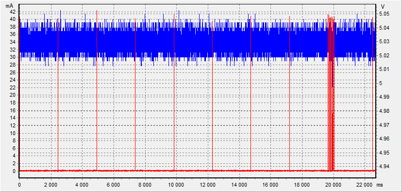
To reduce consumption in LYWSD03MMC, there is only one option - mechanical removal of the LCD controller.
Lithium-thionyl chloride battery 14335 2/3AA PC1 Li-SOCl2 3.6 V will work in the thermometer for more than 10 years. Operating temperature range: from -55°С to +90°С.

@joedupa
Copy link
Author

joedupa commented Feb 27, 2022

Thanks Victor, what is the operating voltage range of the LYWSD03MMC ? The 14335 battery is 3.6V as opposed to 3V CR2032, wouldn't this kill the sensor?

@pvvx
Copy link
Owner

pvvx commented Feb 27, 2022

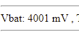
TLSR8251F512ET24: Supply voltage 1.8 - 3.6V
SHTV3, SHT4x: Supply voltage 1.08 - 3.6V

Didn't do any specific tests.
But during the fuss with them, 5V power was supplied more than once. Nothing happened - they work to this day.
To comply with the documentation, it is possible to include any diode in the power circuit.

@pvvx
Copy link
Owner

pvvx commented Feb 27, 2022

USB powered operation (5V):
image
I do not recommend repeating, but if desired, it works with a slight increase in the total current consumption ... :)

The reliability of the SoC is sufficient. But it does not withstand the supply of 12V to the GPIO :) This is also checked - that GPIO will no longer work, but the processor itself and the BLE remain working. :)
This is not Espressif with ESP, but Telink... :)

@pvvx
Copy link
Owner

pvvx commented Feb 27, 2022

image
At 3.6V, something triggers in the chip and the current rises...
image
image
image

@joedupa
Copy link
Author

joedupa commented Feb 28, 2022

Very informative Victor, thanks again, just ordered a couple of those: https://www.aliexpress.com/item/1005003637299772.html

@pvvx pvvx closed this as completed Feb 18, 2023
Sign up for free to join this conversation on GitHub. Already have an account? Sign in to comment
Labels
None yet
Projects
None yet
Development

No branches or pull requests

3 participants