A module has two important moving parts:
- The communication module that is given to the constructor.
- The
processfunction.
The process function has to return. It is the responsibility of the owning code to call process repeatedly. This allows multiple modules on a single system.
The basic template for a module is as follows:
#include <base_module.hpp>

namespace r2d2::module_name {
    class module_c : public base_module_c {
    public:
        /**
         * @param comm
         */
        module_c(base_comm_c &comm)
            : base_module_c(comm) {
            comm.listen_for_frames(
                // Array of frames
            );
        }

        /**
         * Let the module process data.
         */
        void process() override {
            while (comm.has_data()) {
                auto frame = comm.get_data();

                // Process the frame
            }
        }
    }
}
In the constructor, the listen_for_frames method of the communication instance should be called. This will instruct the communication system to deliver these message types to your module.
You need to specify frames you want to receive. This is also the case for requests. Please look at the examples folder for more usage examples.
On naming: the module class should simply be called module_c. The differentiating factor between multiple modules is the namespace in this case. This makes it quite easy to combine multiple modules without knowning class names.
All header locations on the board should be soldered. You can choose if you want male headers, female headers or a combination. We recommend a combination of headers. In the resistor slot, a 3.3k resistor should be soldered. A 3.3k resistor has the color code "orange orange black brown brown" (3, 3, 0, x10, 1%).
The following connections should be made:
- One of the Arduino's should power the board; connect the 3.3v header
- All Arduino's should be connected to a ground pin on the board
- The CAN connection cable should be connected as follows:
- On the Arduino side of the cable, the pin with the diode should be connected to CANTX. The other pin should go into the CANRX
- On the board side of the cable, the pin should go into the header marked CAN.
Either the board has been damaged during the soldering process, or one of the grounds doesn't make a good connection. Things to check for:
- Is there any solder connecting two components that shouldn't be connected (e.g. ground tot 3.3v before the resistor)?
- Are any of the jumper wires broken?
- Are the male or female headers properly connected?
You probably copied test.cpp into the LED module folder. This file is meant as an example and should not be copied to the sources of the LED module!
Check the following things:
- Did you use CANTX/CANRX? These or not the TX and RX pins, those are for UART.
- Did you connect the LED and/or button correctly? Add some cout's in the code to check the value.
- Try another Arduino
The following code should be used to request data from a module on the bus:
// Frame type enum (e.g. frame_type::BUTTON_STATE)
comm.request(frame_type); If your module receives requests from the bus, it should process them in the process function as follows:
while (comm.has_data()) {
    auto frame = comm.get_data();

    // Is this frame a request?
    if (frame.request) {
        // Process request, e.g. read a sensor and send value
    }
}Use the following code to send data on the bus:
// Create an instance of a button state frame
frame_button_state_s button_state;

// Fill the struct with data
button_state.pressed = button.read(); // button is a pin_in

// Send it off!
comm.send(button_state);Sometimes, you want to accept all frame types. That can be done as follows in the constructor of your module:
comm.listen_for_frames({ frame_type::ALL });When using multiple modules on a single microcontroller, each module needs to have its own instance of the communication bus.
You can't reuse the same instance, as that will create conflicts with the listen_for_frames method.
// Wrong
r2d2::comm_c comm;

ns1::module_c mod1(comm);
ns2::module_c mod2(comm);

// Right
r2d2::comm_c comm1;
r2d2::comm_c comm2;

ns1::module_c mod1(comm1);
ns2::module_c mod2(comm2);Usage examples can be found in the "examples" folder. Each subfolder in an example represents a module. These examples are updated to represent the latest version of the library.
For each module, copy the template-arduino folder. Copy the main.cpp and module.hpp to the correct locations in these module folders. The LED has a test.cpp file; this is an example and should not be copied!
To facilitate testing modules using Catch2, a mock bus was created. This bus is instantiated and passed to the constructor of a module. With this bus, you can create packages and inspect how the module responds to them. Please note that the mock bus is only meant for tests; it probably won't work on the microcontroller because it is allowed to use the heap.
Let's say we have a LED module. This LED module receives a ACTIVITY_LED_STATE frame from the bus.
Based on the state given in the frame, it should turn on or off a LED.
This module could be tested as follows:
TEST_CASE("LED module outputs the correct LED state", "[led_module]") {
    // The bus itself doesn't take any constructor arguments
    mock_comm_c mock_bus;

    // hwlib pin_out_store is handy for tests, because it allows
    // us to inspect the current state.
    hwlib::pin_out_store out;

    /*
     * The LED module.
     * The module constructor receives a base_comm_c& and an hwlib::pin_out&.
     * As you can see, using the constructor to receive interfaces on your module really
     * helps with testing and abstraction!
     */
    led::module_c module(mock_bus, out);

    // Create a frame
    auto frame = mock_bus.create_frame<
        frame_type::ACTIVITY_LED_STATE
    >();

    // LED should go to "on"
    // "as_frame_type" interprets the frame as the struct that corresponds
    // to the given enumeration value.
    //
    // E.g. frame_type::ACTIVITY_LED_STATE is matched to frame_activity_led_state_s,
    // so calling as_frame_type with this enumartion value will yield a frame_activity_led_state_s instance.
    //
    // Please note that this data is not copied, it is a non-owning reference to the frame
    // created earlier.
    frame.as_frame_type<frame_type::ACTIVITY_LED_STATE>().state = true;

    // Actually place the frame on the bus, so the module
    // can see and process it.
    mock_bus.accept_frame(frame);

    // Sanity check
    REQUIRE(out.value == false);

    // Manually call the process function on the module
    // to allow it to process everything.
    module.process();

    REQUIRE(out.value == true);
}
In the code snippet above, roughly the following is happening:
- Initialize dependencies: the mock bus and the pin out
- Create the module
- Use the mock bus to create a frame with the given type
- Set a state to a testable value
- Place the frame on the bus
- Let the module process
- Check the result; did the pin_out turn on?
Let's look at another module type; a controller.
The controller receives frames on the bus, and places frames in response.
The mock bus has the get_send_frames function. This function returns all frames that have
been send and allows you to inspect them.
It would look somewhat like this:
/* initialization omitted */

mock_bus.accept_frame(frame);

module.process();

auto frames = mock_bus.get_send_frames();

// Compare the values in frames with the expected resultSending, requesting or receiving on the bus is done using frames. A frame is a ordered collection of bytes that can be sent or received. Frames are defined in frame_types.hpp. Frames are derived from a struct; the struct describes what data the frame contains. A struct is only valid for use as a frame when it is POD type (e.g. std::is_pod is true for the struct). Using non-POD structs is not possible; the code won't compile.
At the moment of writing, sending frames that are larger than 8 bytes is still in development and not yet available. This will be functional and documented in the future.
A frame consists of three parts, all in frame_types.hpp. The first is the enumeration value that refers to the frame:
enum frame_type : frame_id {
    // Don't touch
    NONE = 0,

    // The different frame types
    BUTTON_STATE,
    ACTIVITY_LED_STATE,

    // Don't touch
    COUNT
};
The second one is the actual struct definition:
R2D2_PACK_STRUCT
struct frame_button_state_s {
    bool pressed;
};

R2D2_PACK_STRUCT
struct frame_activity_led_state_s {
    bool state;
};
Please note that the name doesn't reflect whether it is a request, instruction or something else. The name of the struct should simply refer to it's contents, not what it is used for.
You've probably noticed the R2D2_PACK_STRUCT above the struct. This is a macro definition that instructs the compiler to make the struct as small as possible (no padding bytes). This is important, is it makes communication on the CAN bus more efficient.
Struct members should be ordered from large to small. That means uint32_t goes before uint16_t for example.
If you have a frame that is meant purely for Python, replace R2D2_PACK_STRUCT with R2D2_PYTHON_FRAME.
The third one is a macro definition at the bottom of the file. This macro definition connects the enumeration value to the struct type:
R2D2_INTERNAL_FRAME_HELPER(frame_button_state_s, BUTTON_STATE)
R2D2_INTERNAL_FRAME_HELPER(frame_activity_led_state_s, ACTIVITY_LED_STATE)
To prevent clutter of all the structs and enum values, we added a file specifically for all the enum class's. This file can be found here: frame_enums.hpp.
When you have an array in a struct, you can make them more efficient. To do so we can apply one of the available optimisations to the frame. Currently we have two optimisations that can be applied:
- char arrays (
char[]) that are used to send strings - all the other arrays (e.g.
uint32_t[])
The array you want to optimise ALWAYS has to be at the end of the struct. If the optimalisation breaks the rule of ordering sizes from large to small contact: @LRstudent or @itzandroidtab and mention this in the comments / PR.
When you want to have an char array to send strings you can add the R2D2_OPTIMISE_STRING macro to the R2D2_INTERNAL_FRAME_HELPER. You have to put two things in the R2D2_OPTIMISE_STRING macro.
The first parameter is the name of the struct and the second parameter is the name of the variable of the array.
Example of the string optimisation:
R2D2_INTERNAL_FRAME_HELPER(
    frame_display_8x8_character_s,
    DISPLAY_8x8_CHARACTER,
    R2D2_OPTIMISE_STRING(frame_display_8x8_character_s, characters)
)
Important notice!! When using the string optimisation you have to null-terminate the string. Reading after the null-terminator is Undefined Behaviour (UB).
When you have an array in your frame we can apply the R2D2_OPTIMISE_ARRAY macro in the R2D2_INTERNAL_FRAME_HELPER macro. We have to put 3 parameters in this macro.
The first parameter is the name of the struct again. The second parameter is the name of the variable where the length is stored, the third variable is the name of the array again.
Please note the following:
- You are required to have member variable of type
uint8_tthat keeps track of the amount of elements in the array. - The array has to be the last member in the
struct.
Example of the array optimisation
R2D2_INTERNAL_FRAME_HELPER(
    frame_raw_data_s,
    RAW_DATA,
    R2D2_OPTIMISE_ARRAY(frame_raw_data_s, length, data)
)
Important notice!! Reading data after the data[length] is Undefined behaviour.
You should create a Pull Request containing the frame definition you want to add. It has to follow the structure you can see under the previous heading. In short, your PR should contain:
- The enumeration value for your frame
- The struct containing its definition
- The macro connection the enumeration value to the struct
- If you have a frame that is purely for use within Python, please read the next chapter about Python frames.
You should add these values beside the other values/definitions. So the enum value should be inserted into the already existing enumeration. Don't redefine existing structures.
The leads will need to approve and merge the PR. Once merged, the build system will be updated and everyone can pull in the new frame type.
A frame that is meant for use in Python only has a few differences in how it is defined compared to a C++ frame:
- Instead of
R2D2_PACK_STRUCT,R2D2_PYTHON_FRAMEis placed above the struct definition. - In the
INTERNAL_FRAME_HELPER, the struct is poisoned.
You can poison a struct as follows:
 R2D2_INTERNAL_FRAME_HELPER(
       frame_request_map_obstacles_s,
       REQUEST_MAP_OBSTACLES,
       R2D2_POISON_TYPE(frame_request_map_obstacles_s)
   )
Please note the R2D2_POISON_TYPE tag that is placed as a third argument to the helper macro.
Poisoning means that you're disallowing the compiler from using that token.
That means; the struct that is poisoned is not usable in other C++ code.
Since Python frames are not usable in the C++ code, we poison these types to prevent any incorrect usages at compile time.
CAN was chosen because it has the following properties:
- Multi-master by default
- Lossless arbitration
- Fire-and-forget packet-like interface
- Dedicated hardware support on the Arduino Due
- Dedicated pinouts on the Due
- It's a proven industry standard for use in machines and devices (cars, medical, escalators, etc.)
- Relatively high throughput (1 mbit/s, .5 mbit/s of pure data)
Additionally, other modules within the project probably will use the SPI and I2C interfaces.
While the communication system doesn't depend directly on a specific protocol, the Controller Area Network (CAN) bus is used for intra-microcontroller communication. CAN is currently implemented in hardware on the Arduino Due. The protocol is used in a way that is a bit different from general use to fit the R2D2 project better. This doesn't mean the protocol doesn't work with other controllers; everything is within specifications. The CAN standard 2.0B (extended identifiers, up to 1 mbit/s) is used, FD (flexible data rate) is not supported.
The Arduino Due doesn't come with a transceiver for the CAN bus; this is an additional board that can be purchased and connected. While the CAN bus will function without the transceiver, an eye should be kept at the voltages that the different components will put on the bus. CAN is a protocol used in cars, machines and other industrial situations, allowing for a wide variety of voltages and loads. Things like electrical motors can put quite a strain on the bus. Directly connecting the Due to these types of components will likely damage or destroy the Due. Simply connecting two Due's (as is done in this module) is not an issue.
A CAN frame within the project has the following structure:
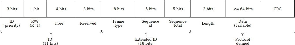
Explanation:
- ID: the priority (channel) of the frame. Lower value = higher priority.
- R/W: whether the frame is a read (request) of write. Write is the default.
- Free: bits not yet assigned.
- Reserved: possibly required to support more than 256 frame types in the future.
- Frame type: the type of the frame (enumeration value)
- Sequence id: the id of this frame in the sequence (e.g. frame id is 27 of 30 frames total)
- Sequence total: the total amount of frames in the sequence
- Length (protocol defined): the length of the data segment
- Data (protocol defined): maximum of 8 bytes
- CRC (protocol defined): the CRC of the frame