X10A already used #40
Comments
|
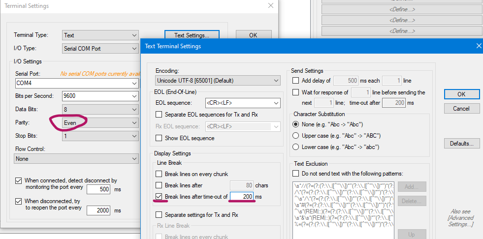
Woah, that's super interesting @Freeman656. We really need to know what is going on this port: If your equipment changes some values on your main unit, that could allow us to understand how it is done and turn ESPAltherma into a controller...! Here is how you could tap into the serial port and record values so we can see what is going on the port: Get one of these USB - TTL module and plug in only the RX port to the TX port of the X10A on your board. Get a serial monitor (eg RealTerm), set the port to 9600, 8E1 and you should see some bytes going. Let us know if you need help with this. You could be able to add ESPAltherma on the same port but it has not been made to share the port and might cause issues with what is using it already. Can you follow these 2 wires from the module to see what is connected to it? |
|
I'm glad to here that this could be useful for further enhancements and would be glad to participate. Also, you can find in the schematics page 23 of this document https://www.daikin.ch/content/dam/document-library/installation-manuals/heat/air-to-water-heat-pump-low-temperature/ehvz-cb3v/EHVZ-S18CB3V_4PFR401672-1B_IM_Installation%20Manuals_French.pdf X10A seems connected to the A6P module (black ISCL-1V3 on the picture). As per documentation, the A5P is the bizone controller, and the A6P is a current loop board (just translated from french, I'm not entirely sure...). This may be a bit specific to have two zones in the house, one is low temp (ground floor), and one is higher temp (1st floor), so I guess this second control board (A5P) is used for additional components linked to the high temp circuit (sensors, water circuit control, etc). I'm still a big anxious about the idea of pluging the ESPAltherma at the same time in the same port.... :) |
|
Let us know if we can be of any help....!
Once we know what there is in parallel we will know how to "share the port" :) |
|
Ah, reading what I wrote ; I'll try to explain more... You should put your RX port of your USB TTL to the RX pin of the X10A port (pin 3), so we can see what the daughter board is sending to the mother board. Note: once you have done this you can also listen to the TX pin of the X10A port to see how it reacts. |
|
Ok I'll try this. |
|
So, I captured around 3-4 minutes of working time. |
|
Hi @Freeman656, Thanks a lot for this! :) Unfortunately, there is nothing much in your file. Only 0xE0 or 0xF0 and a lot of 0x00. edit: added bit stop. |
|
Hi, |
|
Hmm there might just be no communication when you're listening....? Did you chenge your zone temperature setting while capturing? |
|
Ok, rookie mistake, I forgot to hit the 'Change' button in RealTerm for 8E1 ;) |
|
Bonjour @Freeman656! Also, can you confirm that the RX and TX are the one of the X10A main board? (not the one of the dual zone) RX TX |
|
What could help, if you have a second USB TTL is to have the logs in parallel and timed... Because here, I'm not sure which one is the response to what. I do now remember the serial monitoring tool I used it's YAT https://sourceforge.net/projects/y-a-terminal/ If you dont, then I could test a bit or even prepare a project for a serial monitor on ESP32... |
|
Ok I found another USB-to-TTL module in my mess... The X10A I use is the one on the main module of the heat pump. YAT-Log-20210402-081601.log Everything is still pluged in, so don't hesitate, I can do more tests if needed. |
|
Merci @Freeman656 This would make the line cut better. |

|
... and maybe set the timeout to 200ms instead of 500. Thanks! |
|
I'm in the same position. I have Daikin Altherma 3 R F (EHVZ08S23DA9W7) and the X10A is already in use. I have tried now 2 different USB to TTL modules. RX pin of the module is only pin I connect and I connect it to pin 3 of X10A. Every other pin is untouched. I have tried to read serial data with putty, some other program and Open Serial Monitor with settings posted above ( 9600 bps 8 bits, Even parity and 1 bit stop) and I get nothing. I tried to change some settings on Daikin and rebooted it but the serial seems to be quiet. Am I doing something wrong? Maybe this unit uses different settings, is there a way to "analyze" the communication and determine the correct configuration based on that? Edit: I should mention that I do not remove the connector from X10A but rather press the pin of wire from USB-to-TTL to pin 3 (I can see the pin connector under the wire). Should I be able to read data like this without Altherma system reboot? I also tried to change temperature settings from the unit while connected, still nothing. |
|
Hi @kaskii,
|
|
Thanks. Connecting GND did the trick. Here are some files, do they make any sense (I'm not sure what settings I should be using)? Would love to use this project. I bought LAN adapter just before I saw this project. I managed to reverse engineer the adapters websocket protocol but it doesn't provide much data. My ultimate goal is to just get all available data and display it in my custom dashboard. I just need to log these sensor data somewhere and your project seems promising start. |
|
Hey @kaskii, I had a look at your dumps. Now, for your objective of plugging in ESPAlterma in addition to your setup: the communication is too frequent (every sec) to just plug ESPAlterma in addition to the current setup. It's unlikely to break anything (every message has a CRC) but it is also unlikely that you'll get all the expected values. One option would be that ESPAltherma 'listens' to the messages returned by the main board and send its query right after a message, but it is really unsure that the other module would not also try to talk at the same time. What could work in your case is to use a 2 channel relay to switch the serial port to ESPAltherma when it should talk. Basically it would unplug periodically your 'dual zone module', switch the serial port to ESPAltherma to allow for the communication and switch back the the dual zone module when completed. This would mean a 2 channel relay and a little code adjustment to trigger the switch for the communication. Now, there is also a CAN bus in our heat pumps (the P1P2 port). It also can query and set values and it's the one used by the LAN module but I haven't looked at it too much for the moment and I'm not sure you'll have access to the same values. But you can have a look at https://github.com/Arnold-n/P1P2Serial it's an arduino implementation for this bus. |
|
Thank you @raomin for taking time in this, I appreciate it. I had problems with other USB-to-TTL to output anything but I found my old Arduino and used that instead. Here are the files. I'm not sure what settings I should be running with YAT for your convenience, hope these are ok. As for 2 channel relay, would something like this work or do I need some special relays? I don't want to cut wires so I will also buy T-splitters or just connectors to extend current connector - if we can make ESP to work ofcourse. |
|
Yes @kaskii, I was thinking about something like this, you would bridge the signal so they trigger together. Pin3.txt is coherent with what you and @Freeman656 sent thanks. Thanks! |
|
Ah also, I forgot one thing, while logging, if you could change the temp on one zone and note the time when you do, that would be great. |
|
Here are the new files. These timestamps may be off by a second or two. There's no really indicator when the setting is applied and it takes a moment for a relay clicks. I tried to change various zones. 00.02.00 - Zone temp change 00.04.45 -> Strong mode on |
|
Hmm if you look at pin2.txt you can see sequence starting with |
|
I might have found something reading pin2.... did you put your temp up to 30deg? You have no choice of decimal in the temp I presume...? |
|
2 - pin2.txt I forgot how I wired up last time so here are both cases. I actually might have changed the temp to 30 but nothing should be at 19. |
|
Here is new set of files. So around 00.48.50 there was following values in the sensors menu:
The UI "front page" had values:
I changed the language to english and that seemed to mess with the UI. But at least following should be found: I don't see any decimals in the UI for temps. |
|
1 - pin2.txt is now the proper data I was missing. so, my first attempt to understand it makes no sense anymore as the value would now be to... 64 deg. Ah also, I thought that you don't need a relay now to test. Just see how your system behaves when you temporarily disconnect the X10A. |
|
Hi @raomin , Now, a final word about another way to handle this issue. |
|
HI @Freeman656 What I would do to handle this at time where ESPAltherma would need to pool data:
I really think it's the best way to do it. Be conservative at first, only pull data once every 5 min. The proxy way could work but:
|
|
Good points ! |
|
|
I also do have a BiZone. Did someone already manage a solution? |
|
Just had a system installed, can X12A on AP4 be used instead of X10A on AP1? |

|
Wha @glosair, that's a nice finding. Looks like yes, the X10a is propageted to this other one... |
|
Had our HP installed this week, and saw the above, Can confirm X12A appears to work fine with ESPAltherma on my EKCB07CAV3 "Wiring Centre" module.
|

|
Great news ! |
|
Yeah, identical - with Pin 1 (VCC) at the top of the plug =] |
|
I tried the same, and I confirm this is working fine ! @raomin Finally !! It's working ! |
|
Does the x12 connectit exists on Altherma EHVZ08S18DA9W |

Having a look at the installation manual I would say it's the blue connection on A5P but don't hold me to it ;)
https://www.manualslib.com/download/1360382/Daikin-Ehvz04s18da6v.html |

If you look at the green connector above the blue and white ones it appears to be a current loop interface connected to the serial interface (X10A or equivalent) on the heat pump controller. |
|
Spafrost who was your installer? |
|
On the board next to the board with X10a there is indeed another board with X12A.
|

|
Yup |
|
I can confirm as well it works via X12A. Equipment EHVZ08S23E6V bizone using ALTHERMA(BIZONE_CB_04-08KW).h. |
|
That's great news everyone! |
Can some show a picture of the X12A pin configuration ? |
|
It's th same pinout as in the main instructions |
|
For shure but the connector is not orianteted in the same way. |
|
The connector is keyd but top should be pin1 as marked on the PCB |
|
|


|
Yes, that's the badger, will match up with this
[image: image.png]
…On Wed, 19 Oct 2022 at 13:24, haz-69 ***@***.***> wrote:
[image: image]
<https://user-images.githubusercontent.com/74374387/196689734-bb5df2cd-66e7-4ba7-89f3-3a11bbe16667.png>
You mean this is pin1?
[image: IMG_3717 - kopia]
<https://user-images.githubusercontent.com/74374387/196689850-648fffa6-8a94-4ed2-a3c0-dd51c46cab8e.JPG>
—
Reply to this email directly, view it on GitHub
<#40 (comment)>,
or unsubscribe
<https://github.com/notifications/unsubscribe-auth/AN5H5JRI4EB6OSZDDB6RZODWD7R6DANCNFSM4ZXHHGCQ>
.
You are receiving this because you were mentioned.Message ID:
***@***.***>
|
|
I'll take one of the picture and add it to the Readme. Thanks |
|
|

Hi,
First, thank you for your work, it's impressive...
I'm facing some interesting issue with my installation.
Indeed, the X10A is already used by some other component (I guess it's the bi-zone component)
PFA the pictures of this installation, and the ref of the heat pump : EHVZ04S18CB.
I guess, I'm f****d, but if it's possible to used some sort of Y cable or another port than X10A, please tell me.
The text was updated successfully, but these errors were encountered: