CPC CPLINK v0.2 Construction
This pages describes construction of the prototype only very briefly, since this card is now superseded by the v1.0 release version.
Operation of the v0.2 and v1.0 cards is identical from a software point of view and component costs are very similar. However, the XC9536-PC44 CPLD is now hard to find and becoming more expensive, so this version of the card is not recommended for new builds.
A component placement diagram for the board is shown below.
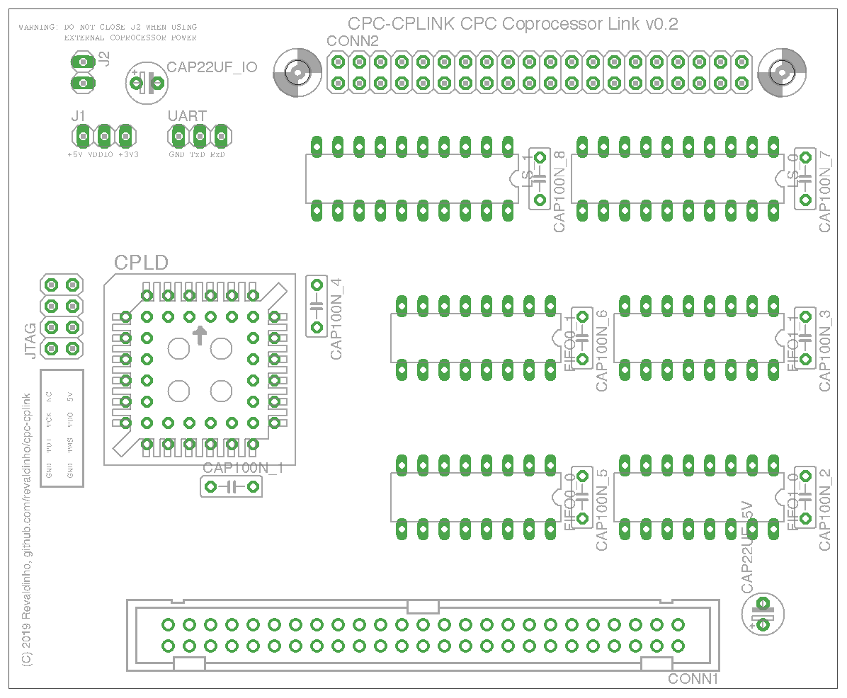
Sockets are recommended for all ICs.
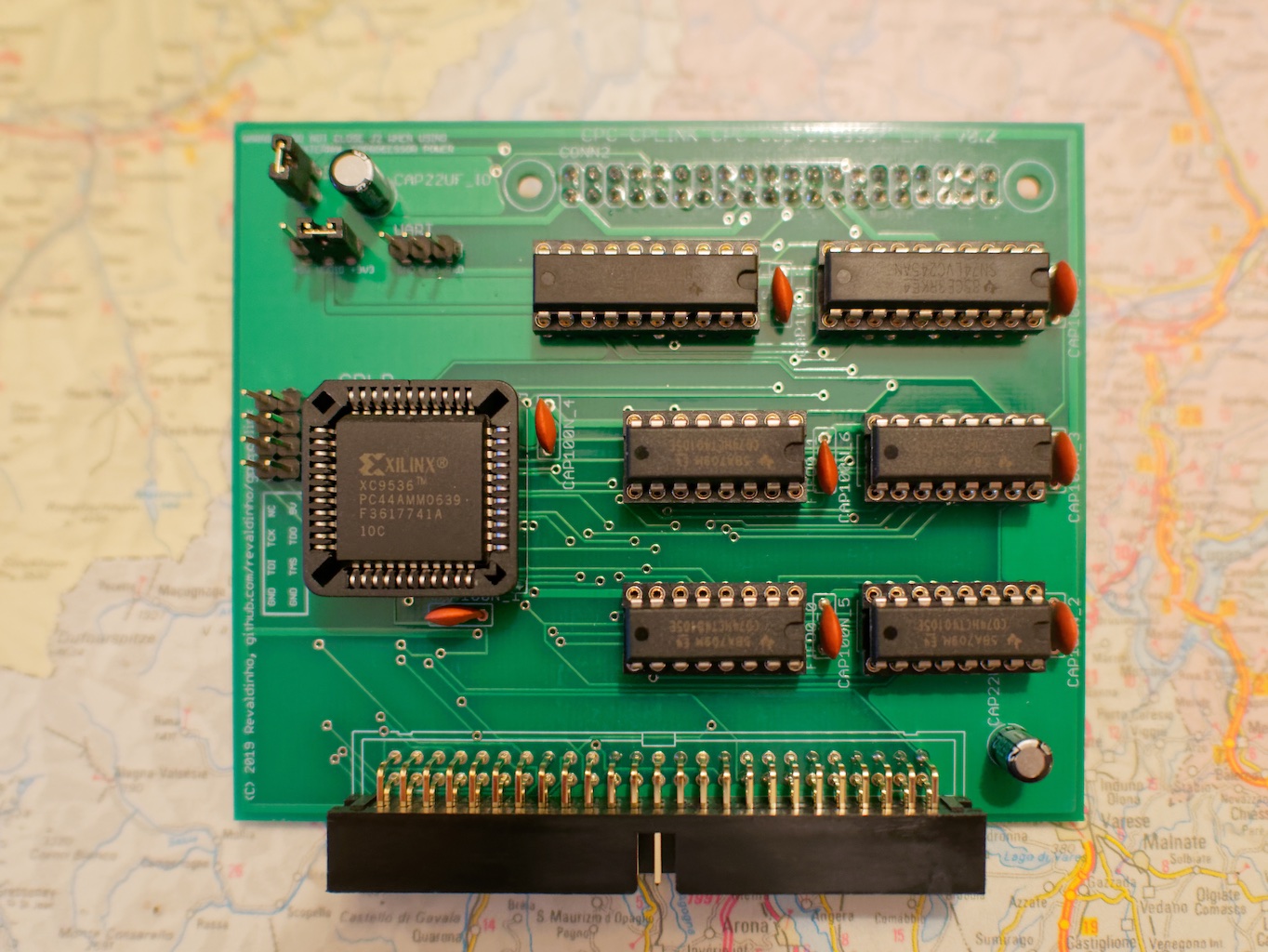
Take care to orient all ICs and sockets exactly as shown in the layout above.
WARNING - do NOT fit a link on J2 if providing external power to the co-processor.
| Part ID | Component | Comment |
|---|---|---|
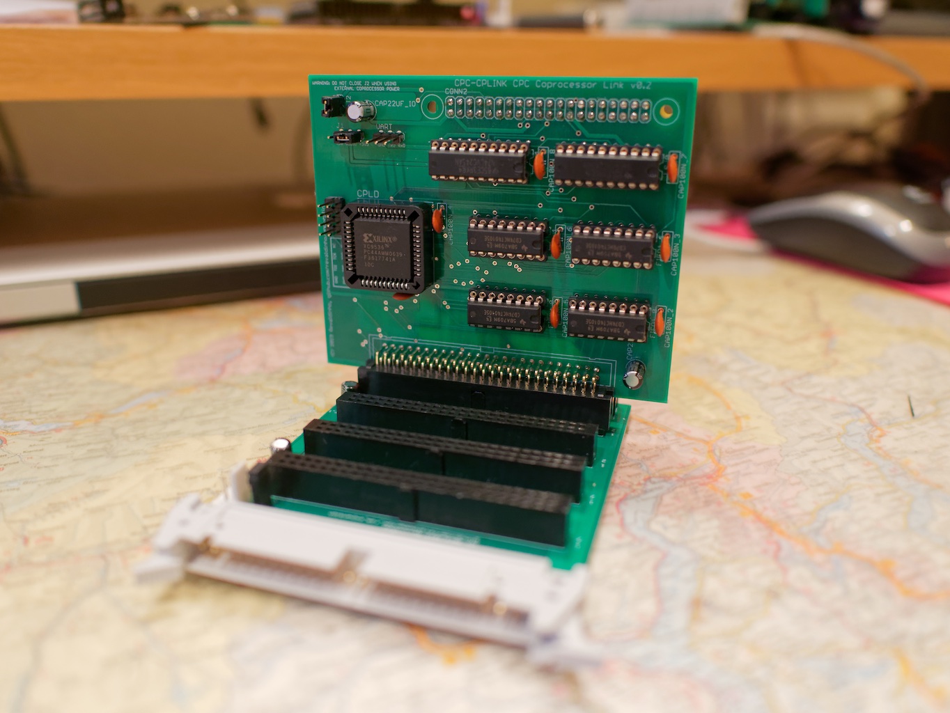
| CONN1 | 50W Right Angled Box Plug | Connector to Amstrad expansion boards |
| CONN2 | 40W Pin or Box socket | Can be fitted to front or back of board depending on slave processor - see below |
| JTAG | 2x5 Pin Header | Xilinx programming header |
| UART | 1x3 Pin Header | Optional serial debugger connection |
| J1 | 1x3 Pin Header | Link for VDDIO voltage |
| J2 | 1x2 Pin Header | Link to provide power to coprocessor socket |
| CPLD | Xilinx XC9536-PC44 OR Xilinx XC9572-PC44 | Xilinx CPLD, NOT -XL type |
| FIFO0_0 | 74HCT40105 | 16x4bit FIFO, CPC -> Copro |
| FIFO0_1 | 74HCT40105 | 16x4bit FIFO, CPC -> Copro |
| FIFO1_0 | 74HCT40105 | 16x4bit FIFO, Copro -> CPC |
| FIFO1_1 | 74HCT40105 | 16x4bit FIFO, Copro -> CPC |
| LS_0 | 74LVC245 | 8 bit level shifting transceiver |
| LS_0 | 74LVC245 | 8 bit level shifting transceiver |
| CAP100N_* | 100nF Cap | Ceramic disc decoupling caps |
| CAP22UF_* | 22uF Cap | Electrolytic capacitors |
The 40W connector pin assignments are shown in the table below.
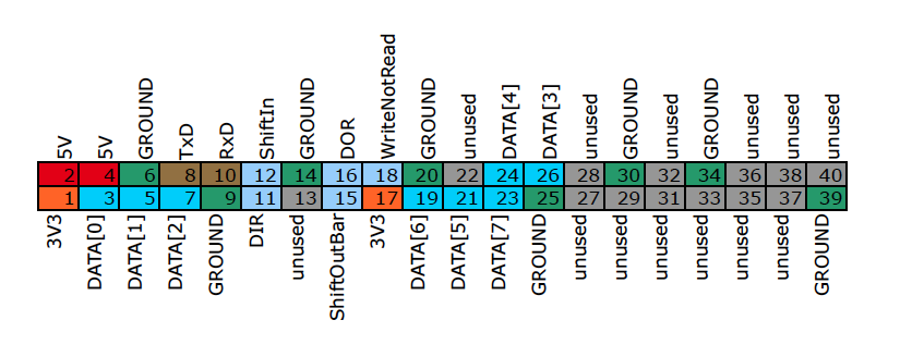
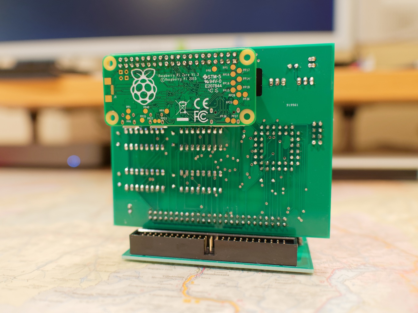
Only the left most 26 pins are used in the co-processor connector to make it plug compatible with older RaspberryPis. Mounting hols are provided for securing a RaspberryPi zero directly on the back of the board (in which case CONN2 should be mounted on the back and either a box socket or pin header chose to mate with the Zero). All other RaspberryPis can be directly plugged into the connector too, although for the larger ones it may be more convenient to use a ribbon cable depending on which of the Pi's other interfaces need to be used.