Custom SW for the "Wifi Stecker Schuko"
WARNING: This devices uses mains power! For good reasons it is not build to be opened and if you do so, you are responsible for your life! Never ever touch it or connect it to your computer when connected to mains.
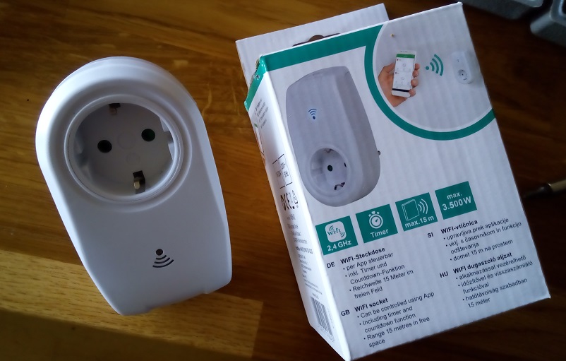
German DIY market OBI is selling a WiFi socket (look for item "OBI 2291706"). It contains an ESP chip, two LEDs, a push button, power supply and a relay in a socket case.
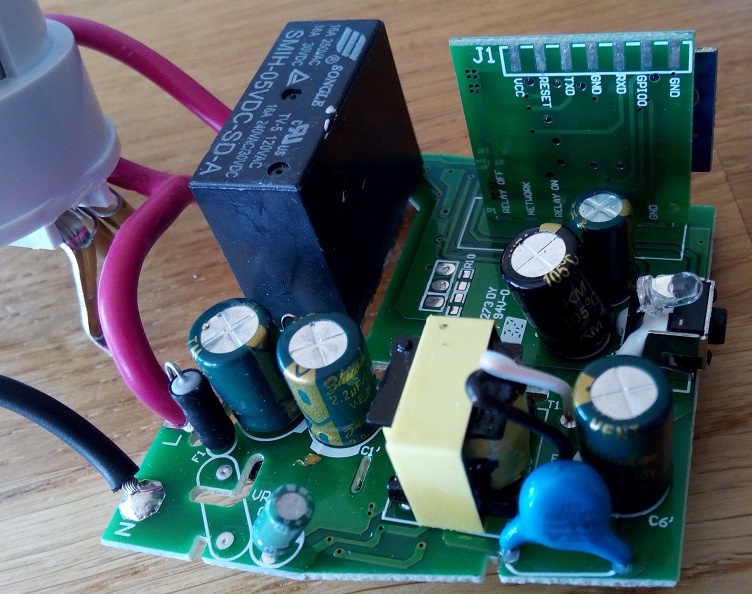
Opening the case is somewhat tricky as they used deep lying "never-seen-before-screws" ("tri-star"), but with a little bit of drilling I managed it. The main board has the relay, the button, two LEDs, the power supply (the low voltage part of my modul runs at about 6.5V), an LDO 3.3V voltage regulator, and an ESP8266 on a separate daughter board:
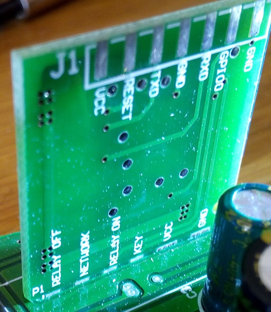
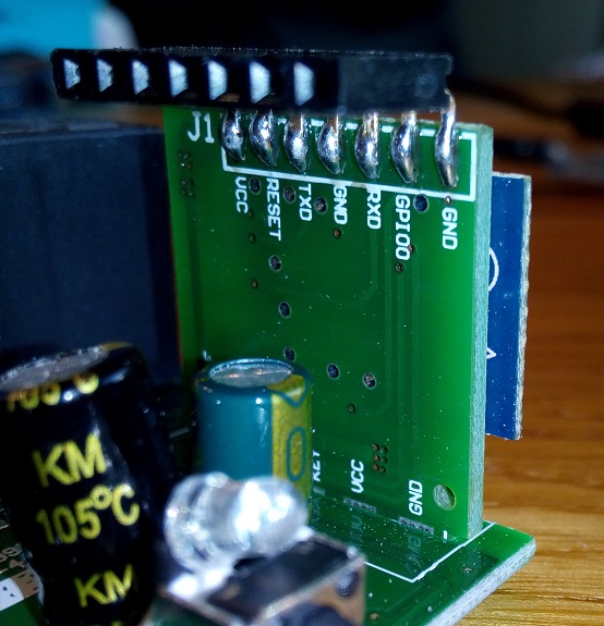
You can nicely read the names of the ESP pins on the daughter board:
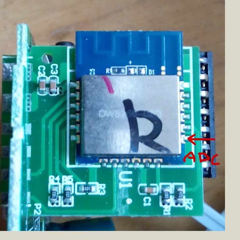
The ESP modul is named "OW8266-02Q" (most probably the same as the WT8266-S1 "Wireless Tag" http://www.seeedstudio.com/document/word/WT8266-S1%20DataSheet%20V1.0.pdf - at least I found the ADC - by trial and error):
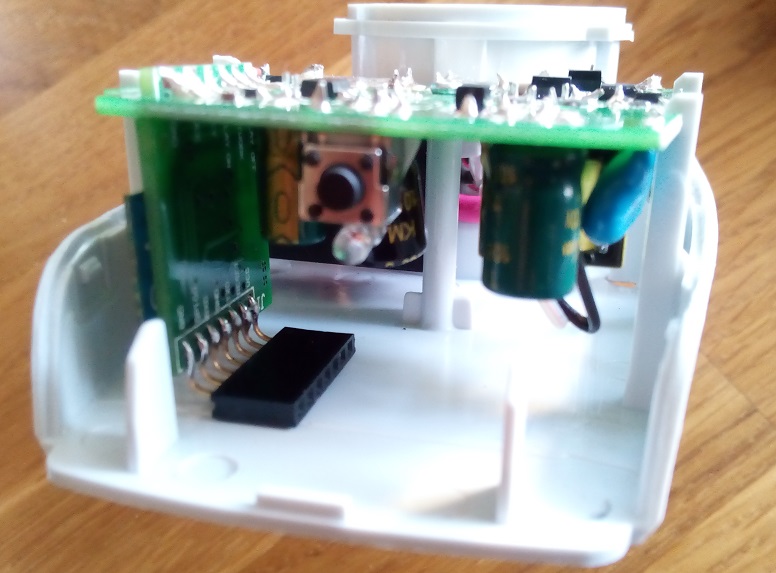
Soldering a pin header onto the board isn't a big deal (I first soldered it on straight and bend it down afterwards):
This even fits into the case when flashing is done:
Flashing follows the usual procedure for the ESP:
- Make sure you are DISCONNECTED from mains power (3,3V is enough)
- Get your USB-UART adapter
- Connect 3,3V, GND, Rx-Tx, Tx-Rx, GPIO0-GND
- Power it up
- Flash it using your favourite flash tool and an appropriate software
The device has the following pin assignment:
- GPIO4 - blue WiFi LED
- GPIO5 - Relay off (LOW pulse)
- GPIO12 - Relay on (LOW pulse)
- GPIO14 - Push Button
It is reported that when holding GPIO12 LOW, the Relay can also be switched by simply turning GPIO5 HIGH and LOW. There is a Tasmota mapping that uses these settings: arendst/Tasmota#1988
Up to now the socket is somewhat smart. But there is plenty of space left in the case, so I decided to make it really smart and add a power measurement. I used an ACS712 hall effect current sensor that converts current values into voltage. I used the 5A version. The ACS712 has to be powered with 5V, so it needs an additional AMS1117-5 voltage regulator. The output of the ACS712 is in the range from 0-5V (with a 0 offset of 2.5V, i.e. if there is no current, the output is 2.5V). Before feeding it into the ESP's ADC it has to be divided with two resistors to 1V max.:
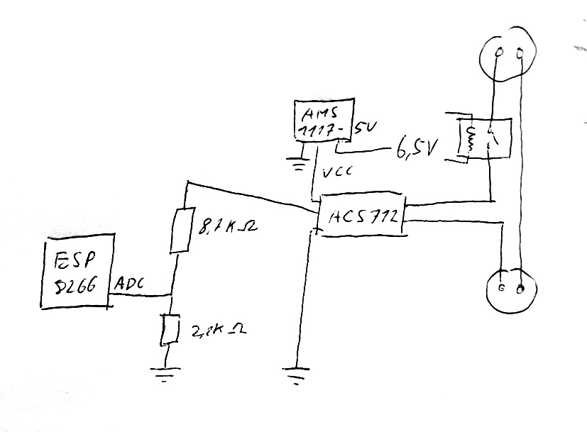
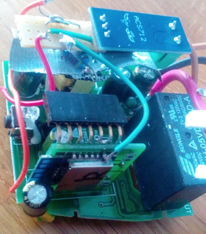
Could be nicer, but it all fits into the case:
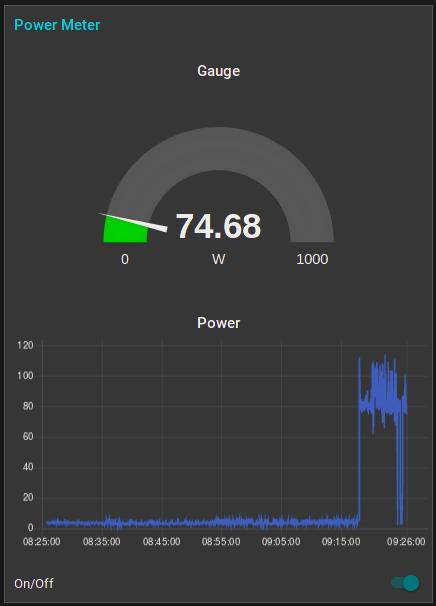
When you are using WiFi, make sure to set wifi_set_sleep_type(NONE_SLEEP_T), otherwise the ADC will produce some more random noise. The Arduino sketch will do the job for a ACS712 with max current of 5A and 230V. It computes the effective voltage by integrating over a multiple of the period and computes the current and the power consumption since the start of the sketch. These values are published via MQTT and can be fed e.g. in NodeRed:
In this repository you find a basic Arduino sketch that reads the pushbutton and connects to an MQTT server (https://github.com/martin-ger/ESP8266-WiFi-Socket/blob/master/OBISocket.ino). Find the basic WiFi and MQTT config in first lines of the sketch.
If you enable the define of ENABLE_POWER_MEASUREMENT, power measurement with the ACS712 will be included.
There is also a sample script for my MQTT Broker/Bridge, an alternative firmware that turns the switch into a OTA programmable MQTT client and broker. For further instructions see: https://github.com/martin-ger/esp_mqtt
On the CLI define the two flash variables @1 with the device number and @2 with the systems prefix and configure WiFi and the remote MQTT broker, e.g.:
set @1 0
set @2 myhome
set ssid MyWiFiSSID
set ap_ssid MQTTbroker
set ap_password stupidPassword
set password MyWiFiPassword
set mqtt_host test.mosquitto.org
Now you can send "0" or "1" MQTT messages to the topic @2/obiswitch/@1/command (in this example "myhome/obiswitch/0/command") and the switch will turn on and off. You can send the messages either to the given remote MQTT broker (in this example "test.mosquitto.org") or to the switch itself (use the IP of the switch). You might connect to the switch eiter via the home WiFi (in this example "MyWiFiSSID") or directly to the AP of the switch (in this example "MQTTbroker" with pw "stupidPassword").
You can also toggle the status locally using the button on the device. The blue LED will start to blink as soon as the switch has WiFi connectivity.
The retained topic @2/obiswitch/@1/status (in this example "myhome/obiswitch/0/status") will always report on the current state of the switch.
Here is this script - you can install it directly OTA via this link: https://raw.githubusercontent.com/martin-ger/ESP8266-WiFi-Socket/master/script.obi