building the board
I won't be discussing here the main unit USB hub replacement - that requires advanced soldering skills, way beyond my par and has a chapter of its own.
Coming back to the board, I didn't (and still don't) have a strong background on soldering stuff - This was actually my first SMD enterprise - but guess what: I enjoyed a lot.
The RF Switch (PE4259) and the LNA (2SC5086) will be more challenging to solder - but entirely doable with an looking glass.
You will also exercise extra care when soldering the UMCC/U.FL connectors, assuring that no solder drops gets to the connector - You will be tossing 1.50 in the trash can if you fail the solder. Careful.
All it took was a thin tip soldering iron - My friend Hugo was kind enough to lend me one of those El Cheapo Amazon USB soldering irons - and oh boy, they are perfect for the job: Thin tip, heats in a jiffy, lightweight, very malleable and comfortable!
Coupled with a rosin pen, thin solder wire and a very well lighted and calm environment - Soldering it was, above all things, FUN. Yes, you can do it!!!
-
Use this circuit board gerber file and order from your favourite PCB fab. I would recommend JLCPCB, all it takes is upload the gerber ZIP file (DO NOT uncompress it) and pay for it. And it is cheap ($2 for 5 boards).
-
The Bill of Materials is provided in a format that contains Digikey's part number - Just upload the BOM .CSV file to Digi-key's shopping cart. It will load automagically in your shopping cart.
A quick note. Thanks to the IC shortage/electronic supply chain disruption, as of now it's been challenging to find the key ICs for this project: RF switch, transistors, voltage regulators.
Revision O - Lite Version currently costs $2 for PCB and around $14 for parts (before shipping & tax).
Consider buying extra quantity of components in order to account for any error/mistake.

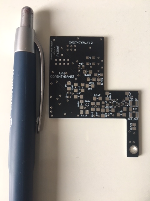
Revision Q Lite Version unpopulated board - top side

Revision Q Lite Version - bottom side
In order to assemble the board, you will need reasonable soldering skills and a steady hand, since this is a small, 100% SMD board and some footprints are really challenging, such as the PE4259 RF switch and the 2SC5086. Estimated effort: Around 1h-1h30 to solder the entire board.
Some devices (all Q and D devices) are ESD-sensitive. So ensure that you have countermeasures against it, especially in low humidity environments.
I also found (the hard way) that the El-Cheapo soldering iron that not only is not isolated, but it is also hot on 5V in its tip! So ensure to not have your board grounded when soldering it, otherwise you might zap the components. You can mitigate it by using a powerbank - since different ground references, it renders the iron essentially isolated.
Another pro-tip: Start soldering the small parts, like the RF switch, the transistors, 0805 capacitors, then move to the larger parts.
Last but not least, after finishing the board, do not skip the obvious testing: checking continuity, looking for shorts in close solderings and a dry run outside the radio checking for heating (use your fingers, you should have no heated components). The board should draw no more than 10 mA in the 13.8V supply line. Check for more information in the upcoming testing section.
Do yourself this favor.
Look ma, no hands!

Revision R, Full version - fully assembled board - bottom side