Example: TCIA Hip Radiograph Rigid Registration
This example demonstrates how xReg utilities and derived programs may be used to rigidly register a patient's hip anatomy (pelvis and each femur) between a 3D CT scan and a real single 2D radiograph. The 3D CT and 2D radiograph image data will be obtained from The Cancer Imaging Archive (TCIA). This differs from the walkthrough examples which only use simulated 2D data.
Although the primary goal is to provide a concrete example for conducting a 2D/3D registration workflow using real data, it does have some clinical relevance. 2D hip radiographs are often collected with the patient in a standing position and enable diagnostics and analysis of the joint under load-bearing scenarios. This is in contrast to 3D CT scans which are nearly always performed with the patient lying supine or prone and the hip joint not under any strain. The 3D models of patient anatomy available from CT are potentially useful for conducting more sophisticated biomechanical analyses of the hip joint during standing. However, since the relative poses of the femurs with respect to the pelvis change as a patient switches between supine/prone and standing positions, using these 3D models is not trivial. The 2D/3D registration process depicted as part of this example enables use of these 3D models for biomechanical analysis by finding the poses of the pelvis and femurs while the patient is in a standing position.
The requirements for running this example are as follows:
- A working build of the xReg library and a subset of the applications:
-
xreg-convert-dicom-radiograph, -
xreg-regi2d3d-replay, -
xreg-draw-xray-scene, -
xreg-create-meshand -
xreg-remap-tile-proj-data.
-
- A working build of the Regi2D3D-IPCAI2020 repository, specifically the
xreg-ipcai-intraop-pelvis-femurs-regiapplication, - 3D Slicer for labeling anatomy and annotating landmarks (example files are provided),
- Ability to download data from TCIA (e.g. via
curl,wgetor web browser).
First, we obtain the 3D CT data using the TCIA REST interface. This data is from the TCGA-BLCA dataset, subject ID: TCGA-G2-A3VY.
The curl command (usually included with most MacOS installations and recent Windows 10 installations) for this is:
curl "https://services.cancerimagingarchive.net/services/v4/TCIA/query/getImage?SeriesInstanceUID=1.3.6.1.4.1.14519.5.2.1.1706.4016.124291161306415775701317569638" > TCGA-G2-A3VY_ct.zip
The corresponding wget command, which is typically used on most Linux installations, is:
wget "https://services.cancerimagingarchive.net/services/v4/TCIA/query/getImage?SeriesInstanceUID=1.3.6.1.4.1.14519.5.2.1.1706.4016.124291161306415775701317569638" -O TCGA-G2-A3VY_ct.zip
Next, we will download some 2D DICOM radiographs using either curl or wget:
curl "https://services.cancerimagingarchive.net/services/v4/TCIA/query/getImage?SeriesInstanceUID=1.3.6.1.4.1.14519.5.2.1.1706.4016.146872675804132000774592060313" > TCGA-G2-A3VY_radiographs_1.zip

curl "https://services.cancerimagingarchive.net/services/v4/TCIA/query/getImage?SeriesInstanceUID=1.3.6.1.4.1.14519.5.2.1.1706.4016.688008491812049140020706213177" > TCGA-G2-A3VY_radiographs_2.zip
wget "https://services.cancerimagingarchive.net/services/v4/TCIA/query/getImage?SeriesInstanceUID=1.3.6.1.4.1.14519.5.2.1.1706.4016.146872675804132000774592060313" -O TCGA-G2-A3VY_radiographs_1.zip

wget "https://services.cancerimagingarchive.net/services/v4/TCIA/query/getImage?SeriesInstanceUID=1.3.6.1.4.1.14519.5.2.1.1706.4016.688008491812049140020706213177" -O TCGA-G2-A3VY_radiographs_2.zip
Next, the CT scan directory of DICOM slices will be converted into a .nii.gz (NIFTI) volume file for further processing. The following commands extract the CT DICOM files:
mkdir ct_dcm
cd ct_dcm
unzip ../TCGA-G2-A3VY_ct.zip
cd ..
This command will convert the DICOM files into a NITFI volume file:
xreg-convert-dicom-vols --one ct_dcm TCGA-G2-A3VY_ct.nii.gz
No interpolation is performed and the original uniform slice spacing (5 mm) and in-plane pixel spacings are perserved (0.65 mm x 0.65 mm).
The --one flag indicates to the tool that only one series is contained in the input directory and therefore only a single volume file will be saved.
The scan may now be loaded in 3D Slicer and should produce views similar to the following:
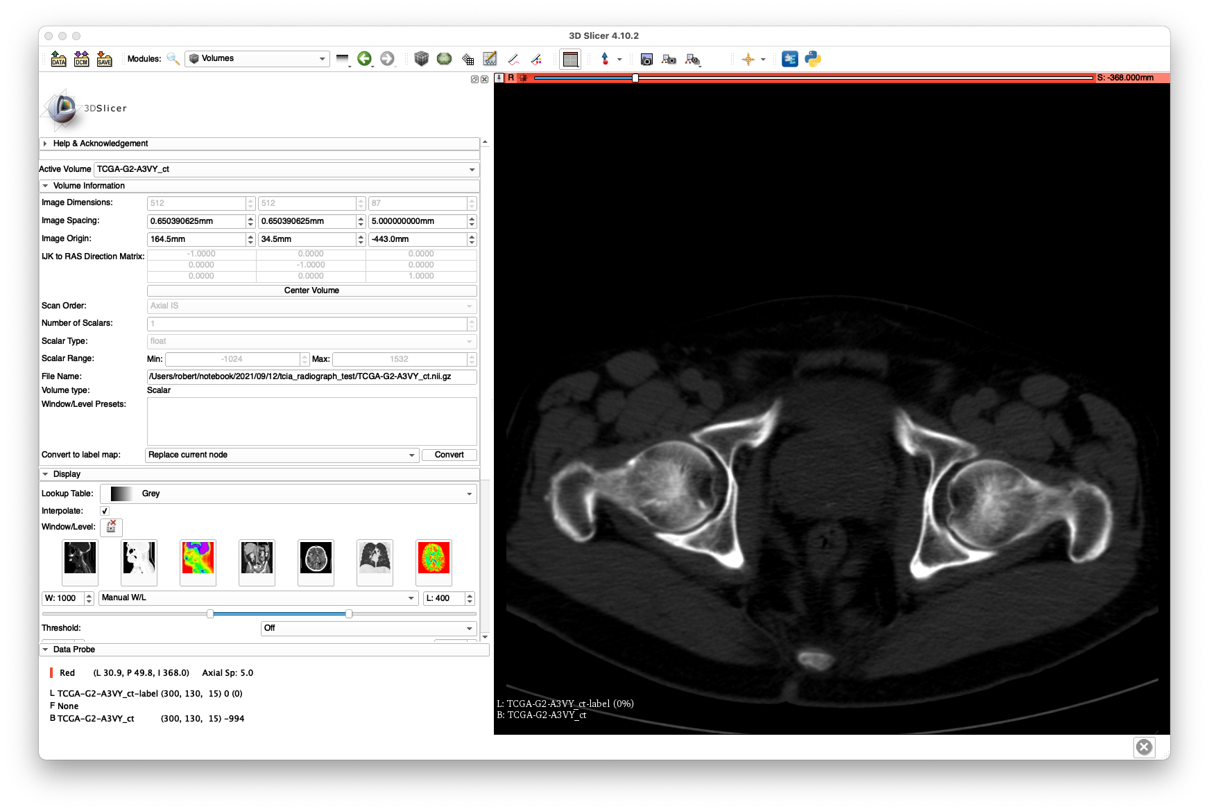
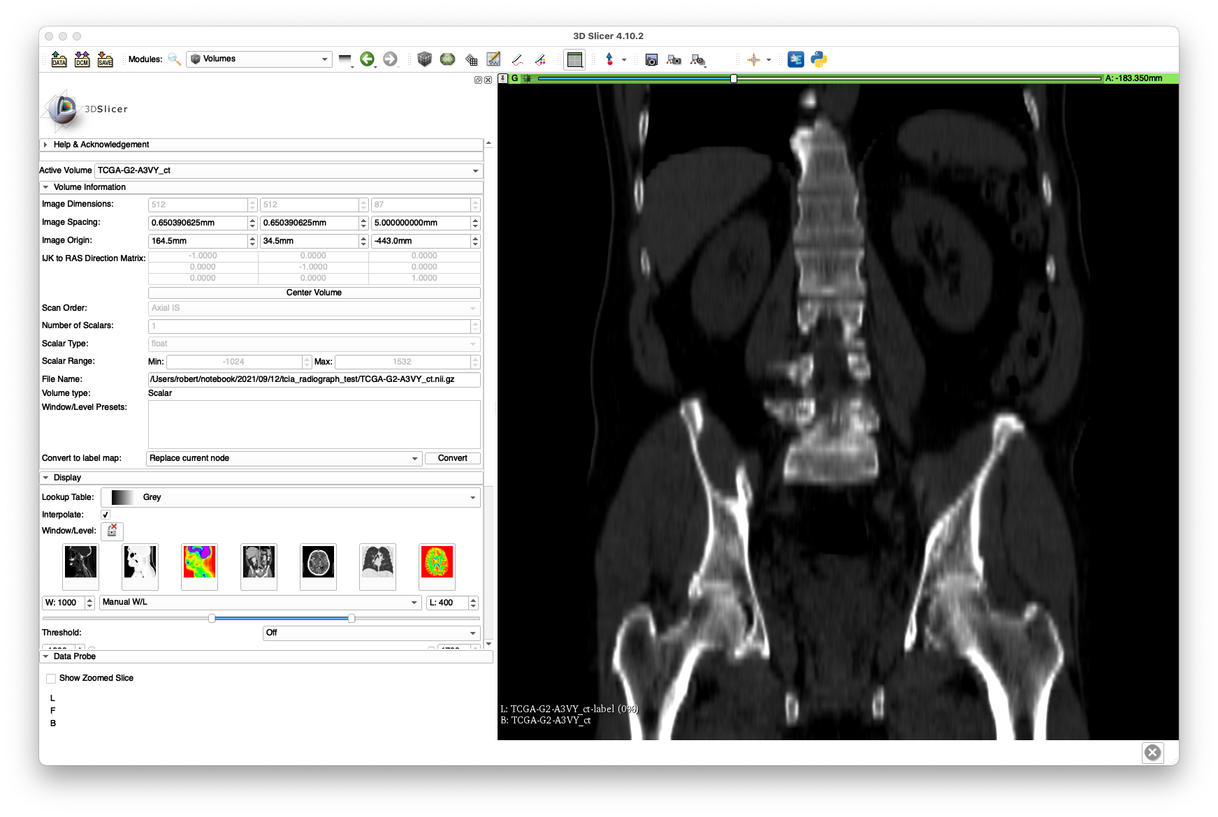 The bluriness of the coronal slice highlights the poor resolution produced by the 5 mm slice spacing.
The SegmentBoneFromCT tool used as part of the walkthrough examples will not work here due to the large slice spacing.
Therefore, we used the "Grow From Seeds" functionality provided by the 3D Slicer Segmentation module along with the level-tracing and some manual touch-up to get the following labelings:
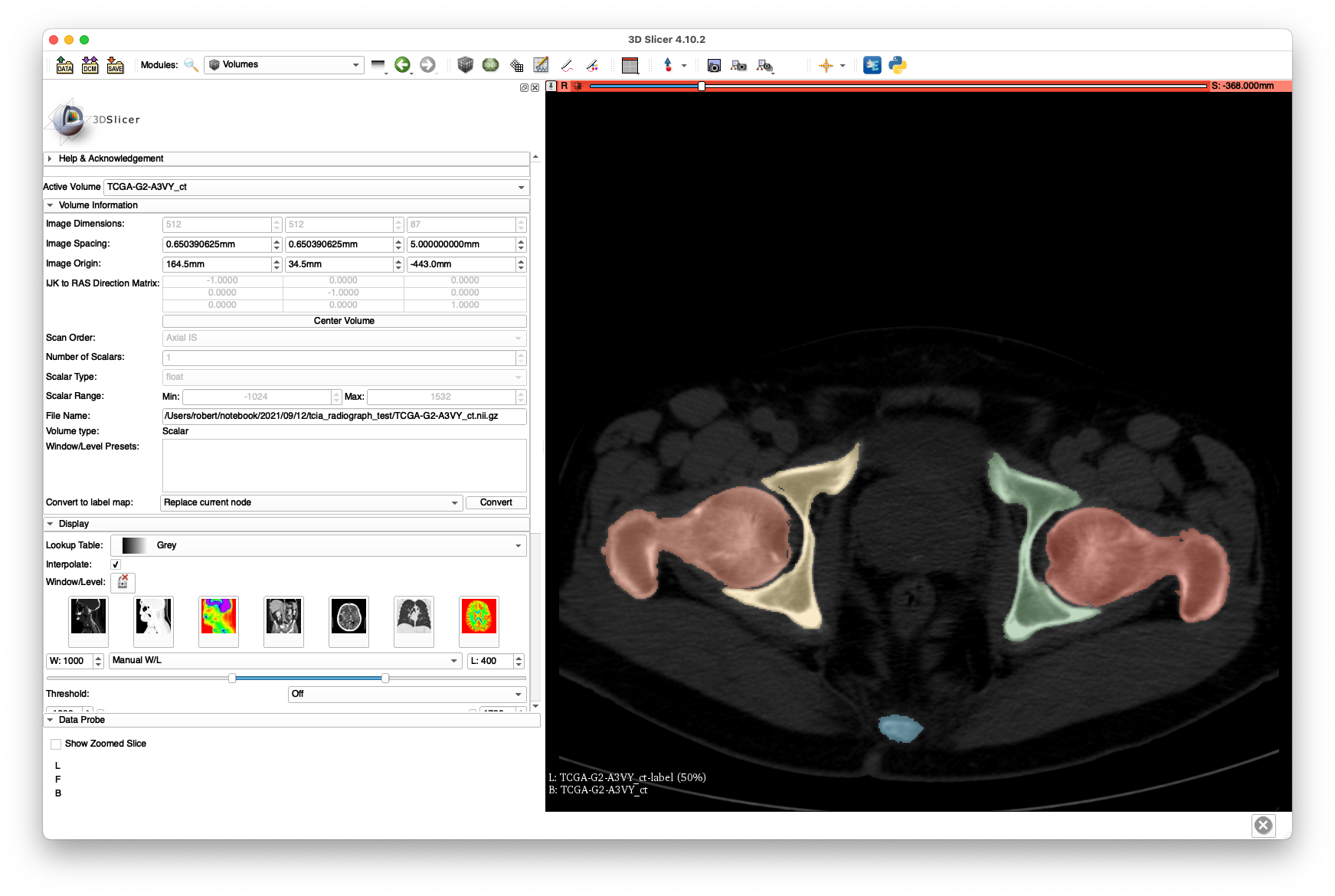
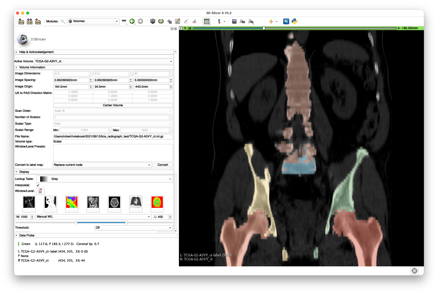
Note that the intra-slice labeling is of decent quality, yet the inter-slice spacing leaves much to be desired. Despite this poor quality, we will see that a successful 2D/3D registration is still possible. No attention was given to segmenting the vertebrae well, as we are only concerned with hip registration.
The labelmap volume is available here.
In order to maintain compatibility with the xreg-ipcai-intraop-pelvis-femurs-regi application that will be used later to perform the 2D/3D registrations, the following labels where used:
- Left hemipelvis
- Right hemiplevis
- Non-sacral vertebrae,
- Sacrum,
- Left femur,
- Right femur.
Next, anatomical landmarks are annotated using 3D Slicer. This is the same set of landmarks described in the single-view pelvis registration walkthrough example.
At the very least, the following landmarks must be annotated:
- Left and right ASIS (
ASIS-landASIS-r), - Left and right inferior pubic symphysis (
IPS-landIPS-r) and - Left and right femoral head centers (
FH-landFH-r).
Besides their use for 2D/3D registration initialization, the ASIS and IPS landmarks will be used to establish the anterior pelvic plane (APP) orientation and the FH landmarks will be used as centers of rotation during the femur registrations.
Examples of these annotations are shown below:
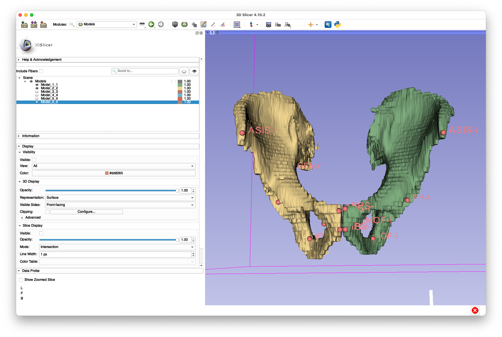
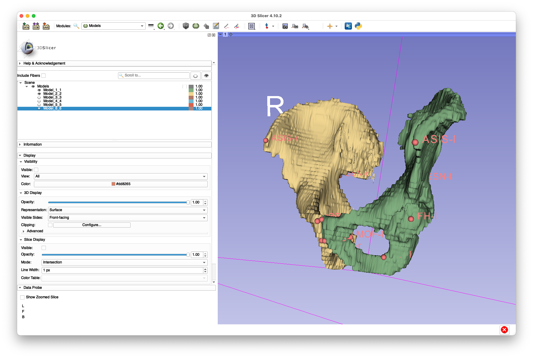
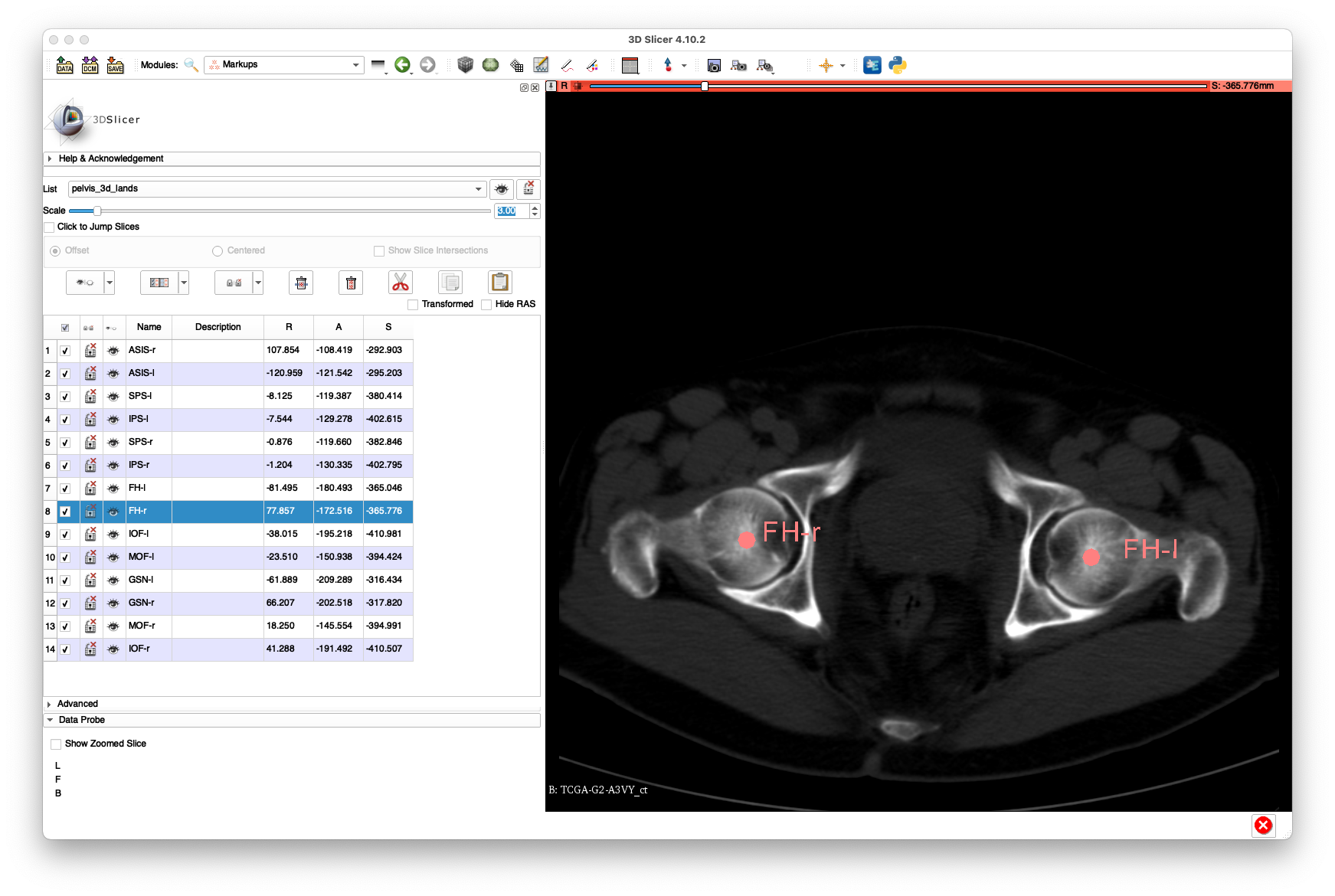
(yes, I know the segmentation looks like it's from the early 1990s)
These annotations are provided in FCSV format here.
The following commands will extract the contents of the radiograph .zip files into a common directory:
mkdir radiograph_dcm
cd radiograph_dcm
unzip ../TCGA-G2-A3VY_radiographs_1.zip
unzip ../TCGA-G2-A3VY_radiographs_2.zip
cd ..
We will be using the following radiographs as part of this example:
-
1-965581fc3af4502514d3669380c44b7f.dcm, -
2-c73e4bdf6c7d19772d00acd2891965fa.dcm, -
1-bd7b5e6f3b5c9bbdf4ec0b5bf7a1f67b.dcm.
Next, we will annotate some of the anatomical landmarks in three of the radiographs. At least four should be annotated per image.
Example annotations for 1-965581fc3af4502514d3669380c44b7f.dcm:
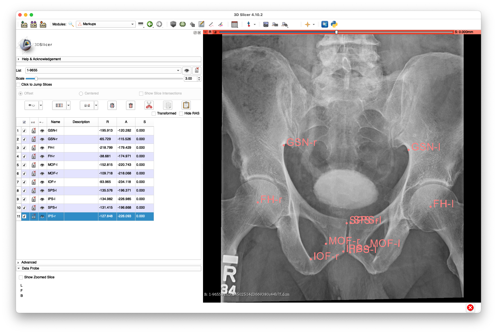 The above annotations are available in FCSV format here.
Note that there is limited visibility of the left and right femurs in this view.
The above annotations are available in FCSV format here.
Note that there is limited visibility of the left and right femurs in this view.
Example annotations for 2-c73e4bdf6c7d19772d00acd2891965fa.dcm:
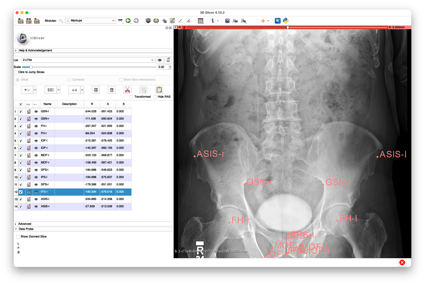 The above annotations are available in FCSV format here.
This view has reasonable visibility of the proximal aspect of the femurs, but no visibility of the femoral shafts.
The above annotations are available in FCSV format here.
This view has reasonable visibility of the proximal aspect of the femurs, but no visibility of the femoral shafts.
Example annotations for 1-bd7b5e6f3b5c9bbdf4ec0b5bf7a1f67b.dcm:
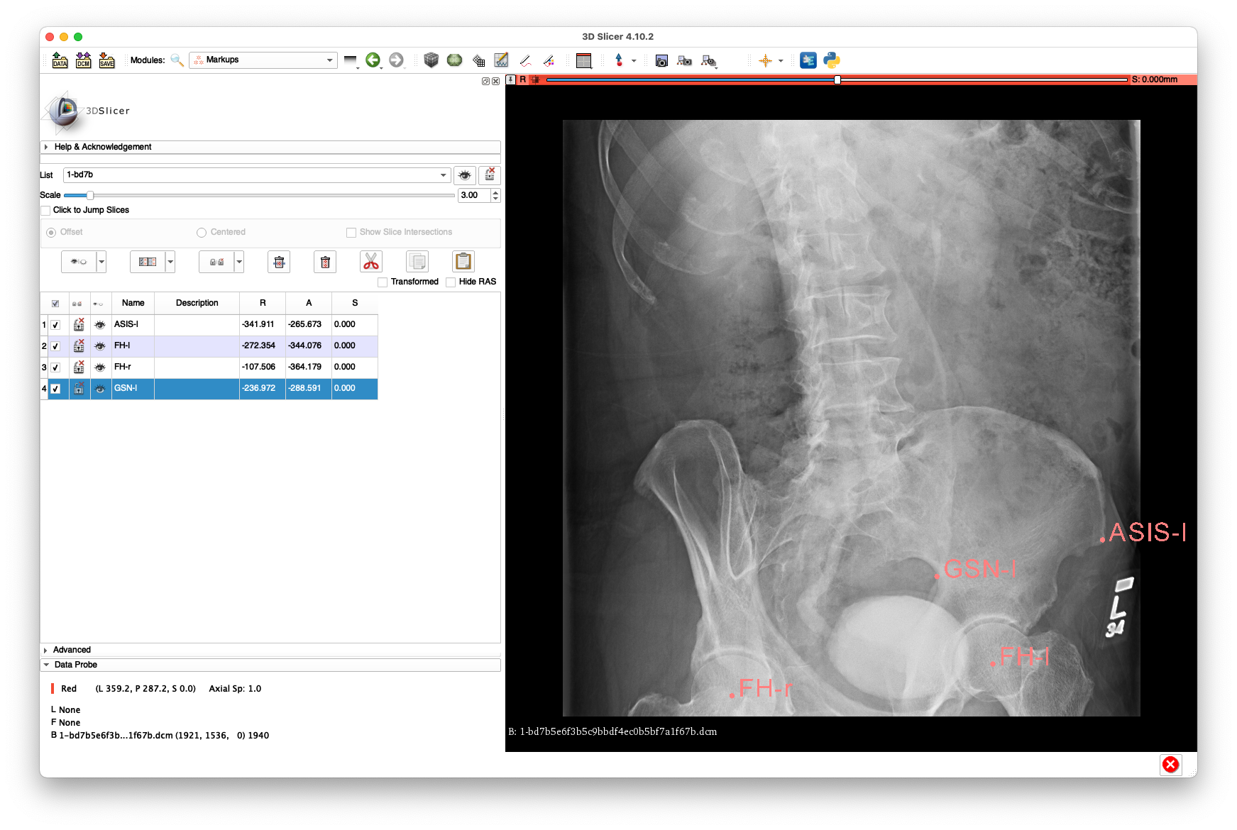 The above annotations are available in FCSV format here.
This view has almost no view of the right femur and very limited visibility of the left femur and is mainly included only to demonstrate the ability to register a non-AP view.
The above annotations are available in FCSV format here.
This view has almost no view of the right femur and very limited visibility of the left femur and is mainly included only to demonstrate the ability to register a non-AP view.
Next, each DICOM radiograph is converted into an HDF5 file compatible with xReg using the xreg-convert-dicom-radiograph tool. This tool also allows the annotated landmarks, stored as .fcsv files, to be imported into the HDF5 file representation.
The following command converts 1-965581fc3af4502514d3669380c44b7f.dcm:
xreg-convert-dicom-radiograph radiograph_dcm/1-965581fc3af4502514d3669380c44b7f.dcm 1-9655_pd.h5 1-9655.fcsv
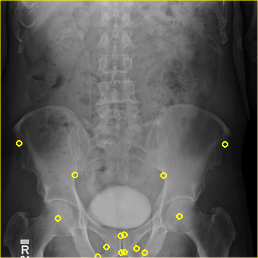
and the xreg-remap-tile-proj-data command is used to verify the data by exporting to a remapped PNG with the landmark annotations indicated:
xreg-remap-tile-proj-data -d 0.25 -o 1-9655_pd.h5 1-9655_remap.png
The -d 0.25 argument indicates that the projection should be downsampled 4x in each 2D dimension and the -o argument indicates that the landmarks should be overlaid.
The remapped projection is shown below:
Next, 2-c73e4bdf6c7d19772d00acd2891965fa.dcm is converted:
xreg-convert-dicom-radiograph radiograph_dcm/2-c73e4bdf6c7d19772d00acd2891965fa.dcm 2-c73e_pd.h5 2-c73e.fcsv
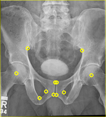
The projection is remapped to PNG:
xreg-remap-tile-proj-data -d 0.25 -o 2-c73e_pd.h5 2-c73e_remap.png
The remapped projection is shown below:
Finally, 1-bd7b5e6f3b5c9bbdf4ec0b5bf7a1f67b.dcm is converted into HDF5:
xreg-convert-dicom-radiograph radiograph_dcm/1-bd7b5e6f3b5c9bbdf4ec0b5bf7a1f67b.dcm 1-bd7b_pd.h5 1-bd7b.fcsv
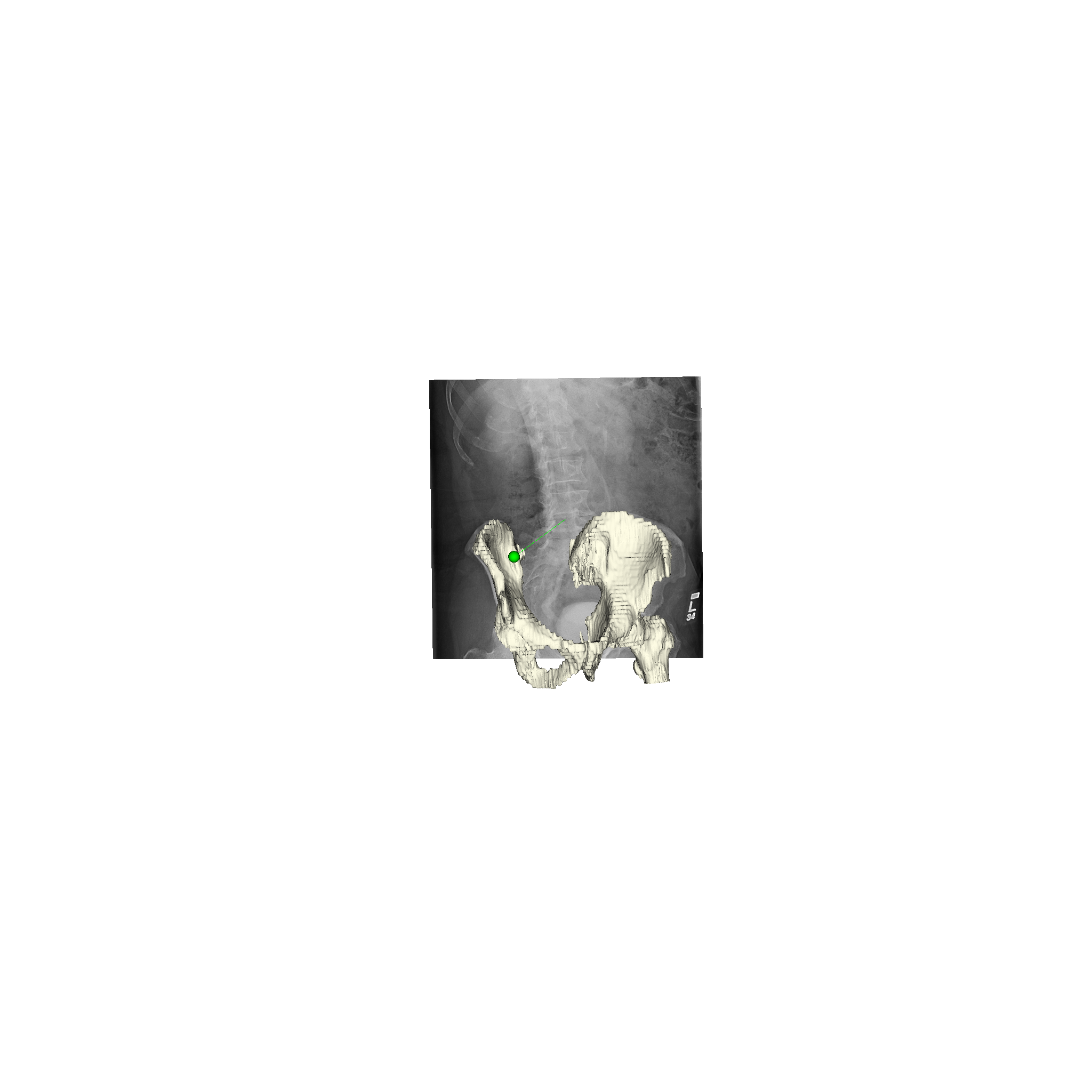
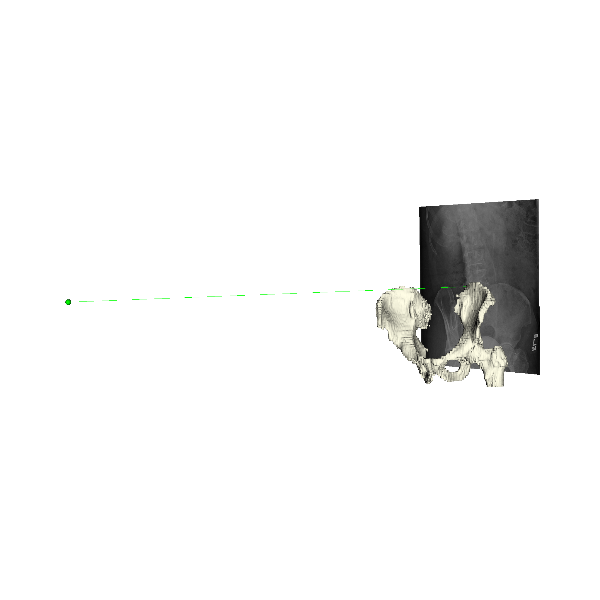
Instead of remapping to a PNG, the projective scene is drawn:
xreg-draw-xray-scene -i -l --bg-color 1 1 1 1-bd7b_pd.h5
The -i flag indicates that the image should be overlaid on the detector plane.
The -l flag indicates that the 2D landmark locations should be indicated with green spheres at their locations on the detector.
--bg-color 1 1 1 indicates that the visualization background should be white, instead of the default shade of blue.
An example of the scene view is shown below:

The converted HDF5 data files are available here:
The xreg-ipcai-intraop-pelvis-femurs-regi tool originally written for intraoperative fluoroscopic registration will be repurposed for the current example.
The tool is part of the Regi2D3D-IPCAI2020 repository which depends on xReg.
The following command will run a registration against 1-9655.
--no-log-remap indicates that no log remapping will be performed - bone is already "bright"/"white."
The 2 positional argument indicates that "method 2," as described in the IPCAI paper, should be used to perform the registration.
"Method 2" essentially solves the PnP problem using corresponding 2D and 3D landmarks in order to get an initial pose of the pelvis.
This initial pose is used to initialize an intensity-based registration of the pelvis, which is followed by a series of intensity-based registrations of the femur.
The free - positional argument after 1-9655_pd.h5 indicates that no 2D segmentation of the radiograph will be used to weight the intensity-based registration objective function.
xreg-ipcai-intraop-pelvis-femurs-regi --no-log-remap 2 TCGA-G2-A3VY_ct.nii.gz TCGA-G2-A3VY_ct-label.nii.gz pelvis_3d_lands.fcsv 1-9655_pd.h5 - pelvis_regi_1-9655.h5 left_femur_regi_1-9655.h5 right_femur_regi_1-9655.h5 left_femur_rel_1-9655.h5 right_femur_rel_1-9655.h5 regi_debug_1-9655.h5
The below command will produce movies that replay each iteration of the registration.
The first movie (edges.mp4) has the measured 2D image that is to be registered as the fixed background and the green edges are features calculated using the estimated pose of the objects which are currently undergoing optimization.
Good alignment of the green edges and the background image most likely indicates that the estimated pose is close to the actual pose of the object(s).
The second movie displays the DRR created using the current estimated poses of each object.
xreg-regi2d3d-replay --proj-ds 0.5 --video-fps 10 regi_debug_1-9655.h5
Using the edge overlay animation as a guide, the pelvis and right femur appear well-aligned. The green edges overlaid near the left lesser trochanter indicate that the left femur is not completely well-aligned. This is most likely caused by small field of view for the left femur.
This next command will run a registration against 2-c73e, which has more visibility of the proximal femurs:
xreg-ipcai-intraop-pelvis-femurs-regi --no-log-remap 2 TCGA-G2-A3VY_ct.nii.gz TCGA-G2-A3VY_ct-label.nii.gz pelvis_3d_lands.fcsv 2-c73e_pd.h5 - pelvis_regi_2-c73e.h5 left_femur_regi_2-c73e.h5 right_femur_regi_2-c73e.h5 left_femur_rel_2-c73e.h5 right_femur_rel_2-c73e.h5 regi_debug_2-c73e.h5
The replay movies are created with the following command:
xreg-regi2d3d-replay --proj-ds 0.5 --video-fps 10 regi_debug_2-c73e.h5
We can see from the edge overlays that the pelvis and both femurs align well. Compared to the previous view, the additional visibility of the greater trochanters of each femur in this projection most likely contributed to the better alignment of the femurs.
Next, a registration against 1-bd7b will be performed:
xreg-ipcai-intraop-pelvis-femurs-regi --no-log-remap 2 TCGA-G2-A3VY_ct.nii.gz TCGA-G2-A3VY_ct-label.nii.gz pelvis_3d_lands.fcsv 1-bd7b_pd.h5 - pelvis_regi_1-bd7b.h5 left_femur_regi_1-bd7b.h5 right_femur_regi_1-bd7b.h5 left_femur_rel_1-bd7b.h5 right_femur_rel_1-bd7b.h5 regi_debug_1-bd7b.h5
The replay movies are created with the following command:
xreg-regi2d3d-replay --proj-ds 0.5 --video-fps 10 regi_debug_1-bd7b.h5
Although the edge overlay movie indicates that the right femur is not aligned, this was to be expected given the small visbility of it in this view. The pelvis appears to register well and the appearance of the left femur's greater trochanter most likely produced the reasonable looking registration of the left femur.
The following commands allow us to visualize the poses of the pelvis and left femur with respect to the projective geometry. The right femur is not included due to the limited field of view.
xreg-create-mesh TCGA-G2-A3VY_ct-label.nii.gz pelvis.ply 1 2
xreg-create-mesh TCGA-G2-A3VY_ct-label.nii.gz left_femur.ply 5
xreg-draw-xray-scene -i 1-bd7b_pd.h5 pelvis.ply pelvis_regi_1-bd7b.h5 left_femur.ply left_femur_regi_1-bd7b.h5  --bg-color 1 1 1 --mesh-color-bone
We can see that the 3D models appear to align very well for this 2D view:
- The 5 mm slice spacing of the CT data in this example restricts our visualization ability (both 3D and registration replay movies). However, it appears that the registration was able to succeed when a sufficient view of the femurs was available. Given that many clinical scan protocols have a minimum slice spacing of 3 mm, it is important that registration should be compatible with lower-resolution data.
- As these radiographs were obtained from TCIA and appear to be focused on the bladder, they are not a perfect example of a clinically relevant application. For example, it is unknown if the patient was actually standing in these views, and if not, the radiographs will not provide any information about the hip joint under load. If anyone is willing to share, or knows of a publically accessible, set of clinically relevant hip radiographs, I would be more than willing to update this example accordingly. We would also expect to see better registration performance, as most hip radiographs show larger views of the femur, including the femoral shafts which are not seen in any of the radiographs used here.
The results shown here are in whole or part based upon data generated by the TCGA Research Network: http://cancergenome.nih.gov/.
- Kirk, S., Lee, Y., Lucchesi, F. R., Aredes, N. D., Gruszauskas, N., Catto, J., … Lemmerman, J. (2016). Radiology Data from The Cancer Genome Atlas Urothelial Bladder Carcinoma [TCGA-BLCA] collection. The Cancer Imaging Archive. http://doi.org/10.7937/K9/TCIA.2016.8LNG8XDR
- Clark K, Vendt B, Smith K, Freymann J, Kirby J, Koppel P, Moore S, Phillips S, Maffitt D, Pringle M, Tarbox L, Prior F. The Cancer Imaging Archive (TCIA): Maintaining and Operating a Public Information Repository, Journal of Digital Imaging, Volume 26, Number 6, December, 2013, pp 1045-1057. (paper)