A soft compiler is a web-based tool that accepts a user-defined robot behavior as a truth table to generate a mathematically optimized circuit diagram that guides the assembly of a soft fluidic circuit. It is used for design of modular pneumatic circuits for soft robots. Detailed information of this tool is available here: https://arxiv.org/abs/2202.03846
- Download the “SoftCompiler” folder in your local drive.
- Enable CORs for your system. a. Follow the instruction given in the below website for windows operating system: https://chrome.google.com/webstore/detail/allow-cors-access-control/lhobafahddgcelffkeicbaginigeejlf?hl=en
- Make sure that CORs are enabled for the website. Once it’s done open the main.html in the web browser.
- You can add the number of input devices by clicking on the “+” button and in a similar way reducing them by clicking on the “–” button.
- Once the required number of inputs are presented with possible combinations in the form of the truth table, select a required output from the given result. Click on 1 or 0 and the color will change.
- To generate the schematic from the desired logic, please select 1 on the output. If not selected, the default value of output is zero.
- Once the desired output from the given input is selected then click generate.
- It will create a sequence of logic along with the input and the output. This needs to be understood properly and accordingly used.
SoftCompiler-2.mp4
- We recommend using the soft compiler for max. 10 inputs.
- Input J is intentionally removed to avoid confusion between I and J.
- The length and diameter of the tubing used to connect inputs and logic devices will decide the flow rate and time required to get the output.
-
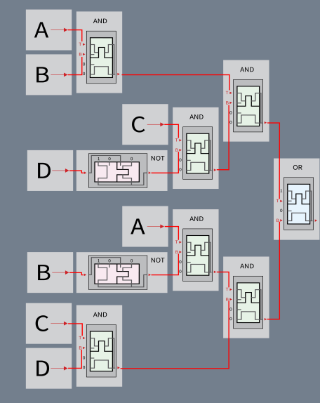
The schematic is organized in terms of inputs, outputs, and logic devices.
-
The inputs are located on the left side and indicated by letters and the output from each logic device is connected horizontally to the next closest logic devices.
-
All soft bistable valves configured as logic gates include red arrows, where some are marked with “T” and “B”, denoting top and bottom chamber respectively.
-
We highly recommend reading the information about fabrication of a soft bistable valve and configuring them as a logic gate from (https://github.com/roboticmaterialsgroup/soft-bistable-valve.)
-
If an input is repeated, the user can choose to add a splitter and connect to several logic gates. Below is an annotated example to understand the schematic.
-
When assembling the fluidic circuit, here are few organizational suggestions:
- Look at how many times an input is repeated in the schematic. Create a splitter with that many outlets before starting the assembly.
- Pre-configure all of the soft logic devices to the correct gate and test before assembly.
- Depending on configuration of soft bistable valve into the logic gates, decide the number of tubes for the circuit.
- Different lengths of tubes will be needed depending on the schematic and logic devices.
- The soft compiler tool offers customization to include the novel logic devices to the family.
- Create similar icons which can be configured as AND, OR, NOT, NAND, or NOR gates and add them to the 'letters' folder.
- When the letters are properly linked, the soft compiler tool can generate the schematic with new/added devices.