See too: Examples and tutorials found on the Internet for using the resources of the STM8
RF magic Controller 6803 IC 133 Modes for Dream Color Chasing 5050 RGB LED Strip (Hardware hacking)
Note: Unfortunately, they are already using an alternative IC to the STM8 (HC89S003A), see here.
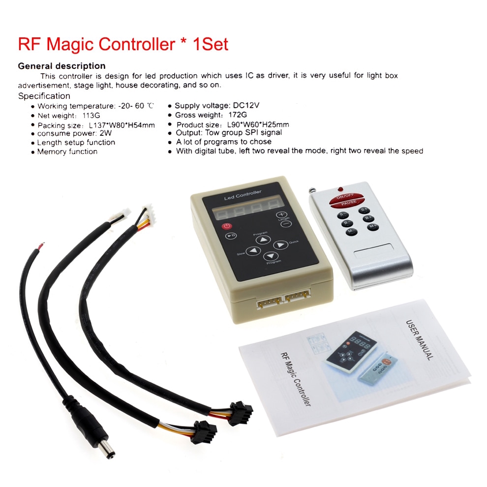
I was interested in using this device for other purposes, so I tried to find out which microcontroller (uC) is used on the controller board. Control board ICs and remote control board IC do not have the codes printed on the housing.
It appears to be an or similar, see the pinout found on the Internet. The VSS (GND), VDD, VCAP and NRST pins are in the same position as the board tracks.
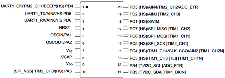
The uC supply is 5V, and apparently the 4-digit display is controlled by some other microcontroller. Apparently the display triggering communication is via serial, and when comparing with the STM8S003F3 pinout, pin 2 is the TX output of UART1.
-
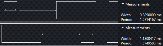
Async Serial 9600 bauds
-
- Display 'H''0''0''1': uC sends 17, 128, 128, 129 (4 bytes, values in decimal, seemingly no gap between data sends)
-
- Display 'H''0''1''7': uC sends 17, 128, 129, 135
-
- Display 'H''1''3''3': uC sends 17, 129, 131, 131
-
- Display 'P''P''P''P': uC sends 25, 25, 25, 25 (Interval between sends: 2 seconds)
-
- Display '5''0''0''1': uC sends 5, 128, 128, 129
-
- Display '5''0''2''8': uC sends 5, 128, 130, 136
-
- Display '5''1''0''0': uC sends 5, 129, 128, 128
-
- Display ' '' '' '' ' (All segments disabled): uC sends '>', '>', '>', '>' (ASCII 62, interval between sends: 2 seconds)
-
Display initialization sequence:
-
- uC sends '$', 164, 164, 164 ('$': ASCII 36)
-
- uC sends '%', 165, 165, 165 ('%': ASCII 37)
-
- uC sends '&', 166, 166, 166 ('&': ASCII 38)
-
- uC sends ''', 167, 167, 167 (''': ASCII 39)
-
- uC sends '(', 168, 168, 168 ('(': ASCII 40)
-
- uC sends ')', 169, 169, 169 (')': ASCII 41)
-
- uC sends '*', 170, 170, 170 ('*': ASCII 42)
-
- uC sends '1', '\t', '0', '3' ('1': ASCII 49; '\t': ASCII 9; '0': ASCII 48; '3': ASCII 51)
-
Sequence of combinations of segments (and characters) accepted in each digit (other values repeat patterns):
-
- Value 17: 'H'
-
- Value 18: seg e
-
- Value 19: seg b, c, d
-
- Value 20: seg g
-
- Value 21: seg d, e, f "L"
-
- Value 23: seg a, b, c, e, f "N"
-
- Value 25: 'P'
-
- Value 28: seg a, e
-
- Value 29: seg a, b, d, e, f
-
- Value 30: seg d, g
-
- Value 31: seg c, d, e, g "o"
-
- Value 34: seg a, g
-
- Value 36: seg a
-
- Value 37: seg a, b
-
- Value 38: seg a, b, c
-
- Value 39: seg a, b, c, d
-
- Value 40: seg a, b, c, d, e
-
- Value 41: seg a, b, c, d, e, f
-
- Value 42: seg a, b, c, d, e, f, g
-
- Value 62: all seg off
-
- Value 64: '0'
-
- Value 65: '1'
-
- Value 66: '2'
-
- Value 67: '3'
-
- Value 68: '4'
-
- Value 69: '5'
-
- Value 70: '6'
-
- Value 71: '7'
-
- Value 72: '8'
-
- Value 73: '9'
-
- Value 74: 'A'
-
- Value 75: 'b'
-
- Value 76: 'C'
-
- Value 77: 'd'
-
- Value 78: 'E'
-
- Value 79: 'F'
-
- Value 93: seg a, b, d, e, f "C'"
Output data appears to be being sent at an incredible 2.4 Mbps. The signal seems to be inverted, with idle logic at 0V (low state), different from the display communication which has high state idle logic. Data capture (display, output control and also the signal from the remote control) are in the Logic folder. Note: Output data is only from the control module, it was not connected to the LED strip.
The remote control transmitter (315MHz) consumes approximately 2.4uA at rest with the 12V battery, model 23A (typical Capacity: 55 mAh to 6.0 Volts). It is recommended not to leave the 12V battery in the remote control transmitter when storing for more than a few days, the battery powers a voltage regulator directly. And when the button is pressed, the consumption is greater than 13mA.
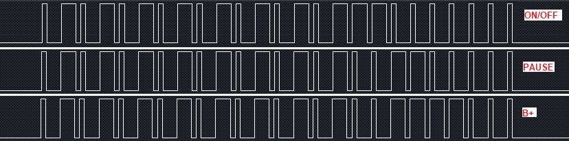
The controller board has an IC that receives the signal from the remote control, this IC has a 6.7458MHz crystal. The signal is passed directly to the uC, like any 433MHz RF receiver. The signal enters pin 12 of the main uC.
For reference only, this video shows the shape of the parts:
- This library is distributed in the hope that it will be useful, but WITHOUT ANY WARRANTY; without even the implied warranty of MERCHANTABILITY or FITNESS FOR A PARTICULAR PURPOSE. See the GNU Lesser General Public License for more details.
[1] ̶W̶a̶r̶n̶i̶n̶g̶:̶ ̶c̶o̶n̶n̶e̶c̶t̶i̶n̶g̶ ̶t̶h̶e̶ ̶S̶T̶-̶L̶i̶n̶k̶ ̶V̶2̶ ̶t̶o̶ ̶t̶h̶e̶ ̶u̶C̶ ̶m̶a̶y̶ ̶d̶a̶m̶a̶g̶e̶ ̶t̶h̶e̶ ̶N̶R̶S̶T̶ ̶i̶n̶p̶u̶t̶.̶.
- For some reason the NRST pin was not able to be kept in a high state (5V) via a pull-up resistor. I found that there was no 1.8V on the VCAP pin, I tried putting a pull-up resistor between the VDD (5V) and the VCAP, after putting the resistor (4k7) on the VCAP, the NRST signal returned to normal, and the VCAP now has 1.8V.
[2] When uploading code via Arduino IDE, the original program will be erased forever, be sure what you are doing.
[3] ST-Link needs to be connected only on the pins:
- NRST
- SWIM
- GND (The board must be powered via the 12V power supply, at the 12V input)