The Feedback Strobe is a technology demonstration aid for EE422G Signals and Systems Laboratory at the University of Kentucky. Commisioned by Dr. Kevin Donohue and Dr. Michael Johnson, the device facilitates hands on involvement in many aspects of a persistence of vision project. The students will be tasked with programming an ARM microcontroller using the Arduino IDE to control both rotation and blink speed of the device in order to produce a persistence of vision effect.
Gonna need some wire. Maybe some pliers for the wires that got tinned super heavy, these breadboards are tight. A bench power supply will be necessary after the all the connections have been made.
When determining the rotation speed, an oscilloscope will probably be handy to for characterizing the output of the reflectance sensor.
A computer with a working install of the Arduino IDE will also be necessary. For the PID part of the lab, a library will have to be installed. Here is a guide on how this is done.
For the Arudino IDE to support cross compiling to the CortexM on the Teensy, Paul Stoffregen's Teensyduino add-on must be downloaded and installed. All platforms are supported. Point the installer at your copy of the IDE and let it install the necessary tools.
Now, in the Tools > Board: menu of the Arduino IDE, a 'Teensy 3.2 / 3.1' option will exist. Choose it. Now make sure you can see an available corresponding serial port in the Tools > Port menu. reset the Teensy if it doesn't show.
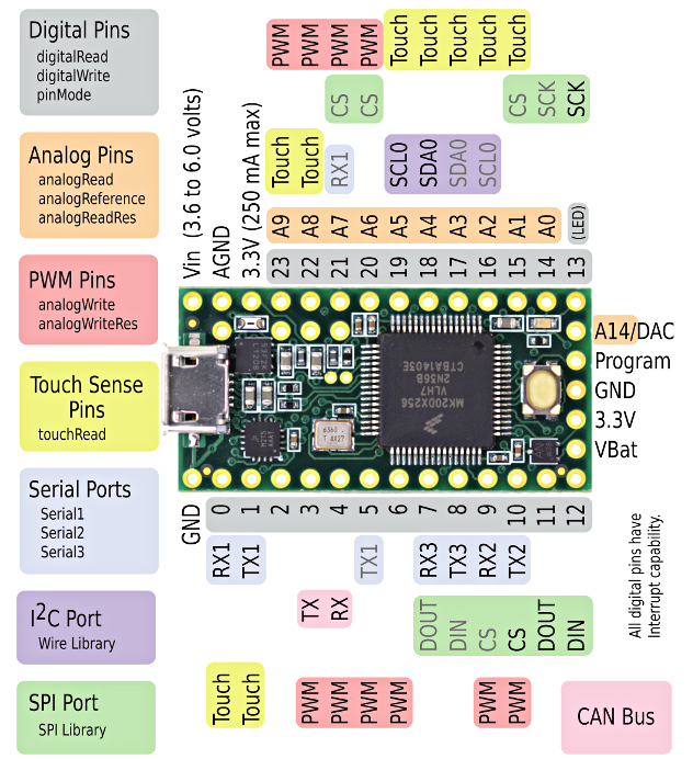
First, the leads of the LED must be mapped to Teensy 3.2 pin numbers. The Figure below shows the color coding of the slip ring wires. Make sure to connect the output of the reflectance sensor to a pin with analogRead() capabilities.

There is an analog reflectance sensor on the underside of the propellor who's signal (the white slip ring wire) varies upon rotation of the propellor. The white pulley on the motor shaft provides a high reflectance surface causing the output of the IR reflectance sensor to decrease. Thus, the analog signal will have local minima upon completion of a rotation.
Slip ring wires can be pinned under the Teensy upon insertion into the breadboard. This eases the breadboarding process.
Any GPIO on the Teensy pins can be used for driving the LEDs.
The IR reflectance sensor can be powered from the Teensy's onboard 3.3V regulator. It is NOT a 5V tolerant IC!
Make sure the reflectance sensor output voltage is least when over the drive pulley. Test that all of the LEDs can be turned both on and off.
The schematic below shows the ciruit to build to interface with the motor. The two thicker red (+) and blue(-) wires are not part of the slip ring 12, they are the motor wires. Connect the (-) to the drain of the MOSFET.

Parts supplied to build this circuit are as follows:
- 1x STP60N N channel MOSFET
- 1x 7805 5V Regulator
- 1x 1N400x Diode (Will have to find another in the lab.)
- 1x 1.5 uF ceramic capacitor
- 1x 0.1 uF ceramic capacitor
- 1x 58 Ohm resistor
- 1x 10 kOhm resistor
The bench power supply should be set to 9 volts
The Teensy is powered from the ouput of the 5V regulator and should be attached to Vin pin on the Teensy.
Make sure to common ground the bench supply and Teensy.
Any pin on the Teensy shown with PWM capability may be used to drive the gate of the MOSFET.
Keep in mind the smallest PWM value will probably not be enough to break the stall torque of the motor, so a baseline minimum PWM that will start the motor will need to be establised.
In order for the motor speed to track the blink rate, PID controller must be implemented. There is a handy PID Library for this exact purpose, with helpful examples for setting up a basic plant.
