ESP8266 based tachometer and speedometer
started in http://modernvespa.com/forum/post2384534#2384534


It has ressetable trip function, shows rpm, exact speed, 0-50 acceleration time and has two colour schemes: one like in picture and another high contrast black on white for sunny days. It hooks up to pickup coil via optocoupler for rpm and i have added hall sensor into original speedo for speed. Based on esp8266 chip and 2.2 inch TFT display.
PARTLIST
Main processing unit is ESP8266 in form of "D1 mini" with ProtoBoard shield. Both can be found at ebay for cheap

Screen is also from ebay, 2.2 inch tft ili9341 320x240, there are several variations of them, mine has 3.3v logic level (no logic level shifter chip). As i use 3.3v to power it, J1 should be shorted by solder.
Step down converter 12V to 5V.

4N35 optocoupler to get RPM from pickup coil. This circuit can be ommited as long as pickup coil generates signal which is up to 3.3V (actually 5v should not hurt chip). It is also possible to use spark plug wire as signal for RPM, just wrap (DO NOIT CONNECT DIRECTLY!!!) few turns of wire around spark plug wire and use schematic from https://github.com/rverzinkevicius/ignition_advance
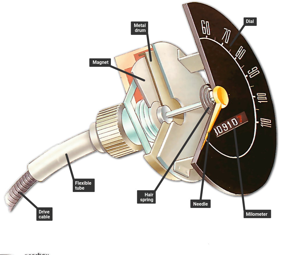
A3144 hall sensor to get speed. Placed inside original speedometer near spinning magnetic disk. Later on have moved to using 5 magnets on wwheel for better accuracy.
1M, 10k, 4.7k resistors
2x 1N4007 diodes. I think one would do the job, but i'm too lazy to remove it and do tests.
25V 10000uF electrolytic capacitor or several in parallel, i have used 6 capacitors 2200uF each. This will provide enough power for D1 mini to save odometer and trip to memory after switching ignition off.
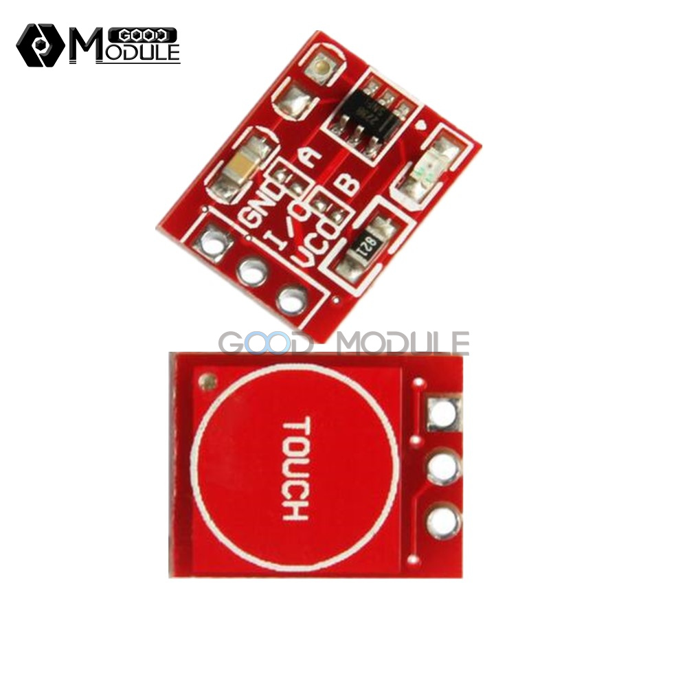
Pushbutton. wired to ground. Short press switches between color schemes, long press (over 3s)- resets trip. It is possible to use capacitive sensor placed behind plastic trim, so no hole drilling etc.
Hand drawn schematic

Pins GND, 5V, 3.3V, RST, A0, D1-D7 are on D1 mini board
Screen connection:
Screen -> D1 mini
Vcc to 3.3V
GND to GND
CS to GND
Reset to D4 (in schematic RST, but we need it on D4 for proper operation)
RS to D3
SCK to D5
SDI to D7
LED to Vcc
SDO not connected
Different screens have different names for pins.

main code is in tacho_speedo.ino
You will nedd to extract TFT_eSPI-master-20200213T100157Z-001.zip to Documents\Arduino\libraries on your PC
There are few things to mention. First you will need to change wheel circumference to reflect your wheel size in meters
float ratas=1.56;
Next you will need to uncomment (remove //) two lines 103 and 104 in code
// odo=0.1;
// allodo=5660.2;
Change allodo to mileage you have on your scooter, upload code to D1 mini, then comment/delete those two lines and again upload code.
To change km to miles, i think it should be enough to multiply your wheel size by 0.621371