The Raspberry Pi is a low cost, single board computer with reasonable performance and relatively low power consumption, typically a version of the Linux operating system, often Raspbian.
The Pi family of boards have turned out to be very useful machines for standalone and/or portable projects such as remote environment monitoring, cameras, etc.
But to be truly portable, a system needs to include a power source and a way to control that power - such as a rechargeable battery, a charger, an on/off switch and some way to monitor battery status.
What I want is something equivalent to the way my iPhone works
- To power it up from a cold state, press a button for a few seconds
- To power it off, press the same button for a few seconds
- Indicate how much power remains in the battery
- Provide an alert when that is running really low
- Shut down safely without any data corruption if the battery does run out
- To recharge the battery, just plug in a cable from a USB charger
This project provides one approach to reaching this goal, building on the LiPoPi project from Daniel Bull.
The system consists of some relatively simple circuitry that links the Pi with a LiPoly battery charger and two Python scripts that handle monitoring and control.
The hardware consists of three subsystems:
1: A Power On / Power Off circuit taken from LiPoPi

2: An Analog-Digital Converter that monitors the battery and USB voltages on the Power Boost

3: Two status LEDs (or an RGB LED)

The software consists of two python scripts:
pi_power.py monitors the battery voltage and handles shutdown of the system when the battery runs out, or when the user pushes a button. It writes the current battery status to a file.
pi_power_leds.py checks the status file and sets a red or green led according to that.
Starting with a powered down system, press the pushbutton and hold for 3 or more seconds. The green activity LED on the Pi will start flickering to show that the system is booting up. At that point you can release the pushbutton. You'll see the boot messages if you have a screen attached.
The two pi_power scripts will start up in background and the power status LEDs will indicate the current status. These will change according to whether or not the USB power cable is connected and the current battery state.
You can safely shutdown the system manually by pressing the pushbutton again. The Pi will shutdown and the PowerBoost will stop providing power to the Pi (the blue PowerBoost LED will go out). If the USB cable is connected, the battery will continue to recharge.
If you let the battery run out, the Red LED will warn you by flashing and when the fraction remaining reaches a low, but safe, level the system will shutdown. The shutdown level is set conservatively to ensure the battery does not drain completely and cause the Pi to lose power.
This plot shows the battery voltage as it drains over times under a load, along with the LED modes.

When the USB power cable is connected to the PowerBoost and the battery is fully charged, the battery voltage is around 4.15V. When that cable is removed, the battery becomes the power source and the voltage drops immediately to around 4.05 V (I'm not sure why...) and then decays down to around 3.7V at which point it can not longer power the Pi.
pi_power sets 4.05V as the 100% power level and 3.75V as 0%, which gives a bit of a buffer at the low end. Between the two levels the voltage decline is close enough to being linear that we can use predict the fraction of battery remaining from the voltage. It's not totally accurate but it is good enough for our purposes here.
The system uses a Adafruit PowerBoost 1000 Charger - Rechargeable 5V Lipo USB Boost @ 1A - 1000C to provide regulated 5V power from a LiPoly battery or a USB power supply. When a USB power supply is attached, the PowerBoost not only powers the RasPi but also recharges the battery. It is a great little device for this sort of project. Adafruit sell it for around $20 and they have a detailed tutorial available.
There are three parts to the hardware side
A momentary pushbutton switch is used to power up the Pi from a cold start and to trigger an orderly shutdown of the system. This machinery is taken from the LiPoPi project from Daniel Bull, which I contributed to. Here is a description of how that works.
The specifics depend on whether you have a RasPi model 3 or earlier.
###Pre-RasPi 3 circuit
To power up from a cold start using the pushbutton:
- The pushbutton pulls the PowerBoost Enable pin high
- The PowerBoost delivers power to the Pi which starts to boot
- GPIO14 on the Pi goes high without any software being run
- GPIO14 keeps the PowerBoost Enable pin high when the pushbutton is released
To shutdown safely using the pushbutton:
- The pi_power.py script monitors GPIO26
- Pressing the pushbutton sends this pin high and the script triggers a safe shutdown
- Shutdown means that GPIO14 is no longer high and so the PowerBoost stops sending power to the Pi
- The diodes isolate the power up and power down functions
- The two diodes in series serve to drop the battery voltage to a safe level for the Pi GPIO pin
Note that it leaves out the low battery component of the LiPoPi project as we can monitor that as part of the battery voltage in the next section.
Note the addition of a 0.1uF ceramic capacitor between GPIO26 and Ground. Without this, GPIO26 would trigger a shutdown whenever I plugged the USB power cable into the PowerBoost. I don't why this happens but it probably because of relatively long wires on the breadboard acting as radio antennae and picking up some sort of spike when the USB cable was connected. This was easily solved, however, by adding the capacitor to smooth out the line to GPIO26.
Try it in your configuration and if you don't need it then leave it out.
###RasPi 3 circuit

The RasPi model 3 changed the way GPIO14 operates. There are two small but important changes to the approach:
Pre-RasPi3 the serial console that uses GPIO14 used a hardware UART and that is what led GPIO14 to be high. RasPi 3 uses a software UART which does not do this. But we can emulate this by enabling the serial console in raspi-config and adding a capacitor across the 100K resistor to smooth the voltage on GPIO14 and keep the PowerBoost Enable pin high.
- Check you have the correct configuration in raspi-config - see Installation below
- Place a 100uF electrolytic capacitor in parallel to the 100K resistor, as shown in this schematic.
I used a 100uF 16V capacitor
This solution was figured out by Daniel Bull and Simon Claessen in the LiPoPi project - all the details are here.
The 100uF capacitor should not be used in the pre-Pi 3 circuit.
To assess how much power is left in a battery we can use the pins on the PowerBoost1000C. The Pi does not have an Analog to Digital Converter (ADC) itself so we need to add an external one in the form of a MCP3008, which is an 8-Channel 10-Bit ADC With SPI Interface. We are only using two channels so this is a bit of an overkill, but they are not expensive (around $4).
The USB pin on the PowerBoost has the voltage of the input USB connection. When the cable is not connected this is 0V and around 5.2V when connected. Nominally, a USB power supply provides 5V but manufacturers often bump this up a little bit to counteract any voltage drop over the supply cables.
The measured USB voltage is used to determine if the cable is attached or not. Doing this via an ADC is overkill but as we need the ADC for the battery voltage, it makes sense to use it.
The Battery voltage on the Bat pin is what really tells us the current battery status. This has the output voltage of the LiPoly battery, which varies from 3.7V when depleted to around 4.2V when fully charged.
The maximum input voltage for the analog side of the ADC is 3.3V so we need to reduce the PowerBoost voltages using a pair of resistors acting as a Voltage Divider. In this case a combination of 6.8K and 10K resistors brings the maximum input voltages into the desired range.
The ADC uses the SPI interface on the RaspberryPi side which uses four GPIO pins. The code for this interface was written by the Adafruit team and manages SPI in software, as opposed to the Pi's hardware SPI interface, so you can choose other GPIO pins if necessary.
Note that this is a schematic and does not correspond to the actual chip pinout.
The system needs a way to tell the user how much power remains in the battery. One of the simplest ways is to control a Red and Green LED from the RasPi to implement a simple interface - green is good, red means low battery.
Even better is to use an RGB LED and control the red and green components - you can even get yellow. Most RGB LEDs are Common Anode which means you need to use this circuit.
But you can use individual LEDs and wire them like this

If you do this you will want to edit the pi_power_leds.py and comment/uncomment the relevant lines - see the comments in the code.
Note the breadboard diagram shows two individual LEDs in this 'common cathode' arrangement.
Wiring all this up on a breadboard gets you something like this:

Here is a larger version of this layout
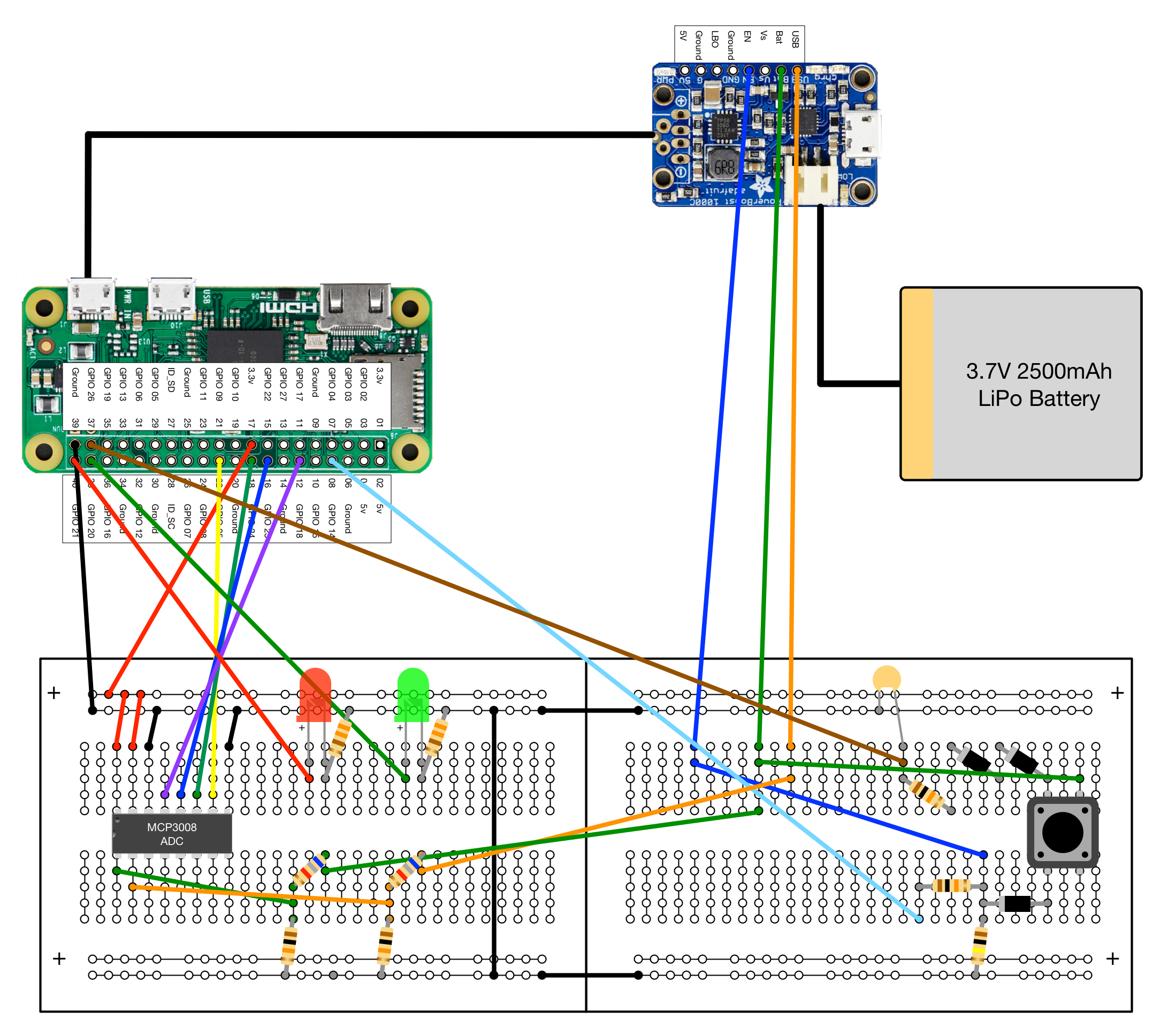
And here is what my actual breadboard looks like - not pretty, but functional

The breadboard layout was created to make the circuit easy to understand (you may argue whether or not I succeeded...). One consequence of that is that a number of the jumper wires are relatively long, compared to a compact circuit board. This may have a couple of unwanted side effects.
Long wires attached to RasPi GPIO pins may act as radio aerials. Even though the code uses internal pull-down resistors to avoid the pins from floating, I did have a problem with the shutdown pin (GPIO26 in the circuit) getting triggered when I plugged the PowerBoost 1000C input USB cable back in, after it had been disconnected. I solved that by placing a 0.1uF ceramic capacitor between GPIO26 and Ground.
In addition, there can be voltage drop over longer wires and the breadboard tracks. The Adafruit guide to the PowerBoost 1000C mentions this. Shorter wires are better
Please do not just wire your circuit from the breadboard diagram - understand the circuit first - you may be able to come up with a neater layout and, more importantly, I may have made a mistake in creating the diagram.
Here is a photo of another breadboard layout where I've gone for a more compact layout. Note that the wires are much shorter and I did not need the 0.1uF capacitor on the power down circuit.

The software end of Pi Power is split into two components.
pi_power.py does all the work. It monitors the battery, handles the power down process as well as shutting down the Pi is the battery runs out. It checks the battery every minute and records the current status in the file /home/pi/.pi_power_status.
In general it is intended to run as a background process that starts up automatically when the Pi boots up.
For testing you can run it from a shell. It can take three options:
- --debug will output the battery and USB voltages every time it checks (once a minute)
- --log outputs the same information to the file pi_power_log.csv which you can use to generate a plot of voltage over time
- --safe delays system shutdown by 2 minutes. See the installation section for how this can be used.
There are many ways to inform the user about the power status. You might have a numeric display on a screen, or a bar graph like you get on some phones. Separating the monitoring and display components makes it easier for others to build different displays.
I have chosen the simple approach here of using a Red and Green LED to indicate the general power status. pi_power_leds.py checks the status file and sets either led according to that. It is easy to change the specific LED patterns but the default ones are:
- Green, Blinking - USB power source is connected - Battery is charging
- Green, Constant - Battery - more than 25% of battery remains
- Red, Constant - Battery - more than 15% of battery remains
- Red, Blinking - Battery - more than 10% of battery remains
- Red, Blinking Fast - Battery - less than 10% of battery remains - system will shutdown soon
Here is a plot of battery voltage over time, marked to show how the LED modes correspond to voltage (RasPi Zero and 2700mAh battery)
The script checks the status file every 30 seconds so there can be a delay between, say, plugging in a USB supply and the LEDs updating. Reducing the poll interval would improve this.
The Power Up function relies on GPIO14 which is used for the RasPi UART serial interface. Before installing the pi_power scripts, you need to configure this as follows:
If you have a RasPi pre-model 3:
Run sudo raspi-config and under "Advanced Options" select "Serial" followed by No. This prevents the Pi using GPIO 14 for the console (which would shut off the power).
If you have a RasPi model 3:
Run sudo raspi-config and under "Advanced Options" select "Serial" followed by Yes. This should be the default
Python on the Pi - if you do not have Python and the Rpi.GPIO library installed on your Pi then you will need to do the following
sudo apt-get update
sudo apt-get dist-upgrade

sudo apt-get install python-dev

sudo apt-get install python-setuptools
sudo easy_install rpi.gpioThe following assumes you have the hardware set up to use the GPIO pins as shown above
Boot your Pi and download pi_power.py and pi_power_leds.py and make them executable with chmod a+x pi_power.py etc.
Run the scripts in a terminal window, using the --debug option for pi_power.py.
$ ./pi_power_leds.py &
$ ./pi_power_debug.py --debug
[...]
Make sure eveything works as expected - the LEDs show the correct status, you can shutdown and restart the system, etc. You want to test all the functions:
- Power on from the pushbutton
- Power down a running system from the pushbutton
- Check all LED modes with and without USB cable, allowing the system to drain the battery
- Allow the battery to drain and trigger a low battery shutdown
Depending on the size of your battery, this can take some time but you need to test it thoroughly before making the scripts start on boot.
Both scripts are intended to be run as silent background processes that start up when the Pi boots.
NOTE The Pi boot process is different from other Linux systems in that there is no single-user mode. That makes it difficult to fix problems in start up scripts like this as you have no easy way to run the system up to, but not including, the problem script. So... test everything really well before you put them in a system start up script
To do this you want to add the full paths to the scripts to /etc/rc.local.
/home/pi/pi_power_leds.py &
/home/pi/pi_power.py --safe &
Note the --safe option. Use this while you are testing. It delays the system shutdown for two minutes. Certain errors in your circuit can trigger an immediate shutdown. If you run into that, this delay gives you two minutes to edit rc.local and comment out the lines while you fix the problem.
Once you have tested your system and you are confident that all is well, you can remove the --safe option.
/home/pi/pi_power_leds.py &
/home/pi/pi_power.py &
And that's it... hope you like it...
Pi Power has been tested successfully on these boards:
- Raspberry Pi 2 Model B V1.1 (2014)
- Raspberry Pi Zero v1.2 (2015)
- Raspberry Pi 3 Model B V1.2 (2015) - using the Pi 3 modification shown above
Please take a look at the Wiki for more background on battery charging, power usage by the Pi etc.
The power on / power off machinery is taken from the LiPoPi project from Daniel Bull, which I have contributed to. If you want a simpler solution without the voltage monitoring machinery then LiPoPi might be just what you need.
Currently there is no way for the software to know when the battery is fully charged. On the PowerBoost, the yellow charging LED changes to Green, so the information is available. There is just no easy way to get it to the Pi. Accurately estimating it from the voltage does not seem to work well in practice.
Adafruit also sell the PowerBoost 500C charger. This can output a maximum current of 500mA as opposed to the 1A of the 1000C. More importantly, the 500C can power its output or charge the battery, but not both. The 1000C can charge the battery while powering the Pi, so this is the one to use.
One downside of the power on / power off mechanism is that you can no longer reboot the machine using the shutdown -r now command. The system will shutdown the PowerBoost which cuts power for the reboot. Simply shutdown and hit the pushbutton to get the same effect.
For a mobile system you may be tempted to skip the bulky USB cable between the PowerBoost and the Pi and just wire the output 5V and Ground to the corresponding pins on the GPIO header. This does work but is not recommended as it appears to bypass a power control circuit on the Pi. With a HDMI display plugged into the Pi with this configuration, the Blue output LED on the PowerBoost flickers dimly, suggesting some current path back to the PowerBoost from the HDMI display. I have not been able to troubleshoot this further.