Documentation in English
- Editing an existing Ikarus profile
- Provisions for the graphics used
- Windows screen settings and Ikarus configuration
Ikarus is a software to create and use Virtual Cockpits for the flight simulator DCS World. For more than 400 instruments of various aircraft and helicopters are provided. In addition, there are different types of switches to communicate with the simulator via the Virtual Cockpit.
The latest version of Ikarus can be found on our GitHub page at https://github.com/s-d-a/Ikarus/archive/master.zip Marked as Stable Versions of Ikarus can be found on our GitHub page at Release ( https://github.com/s-d-a/ikarus/releases ).
Download the appropriate version and extract the zip file to a location of your choice, eg "This PC → Documents".
Ikarus does not need to be installed, you can run it right after unzipping.
For the displays Ikarus needs some special fonts. These are located in the subfolder Font and must be installed in Windows. Double-click on the font and then click on "Install".
To start Ikarus switch to the subfolder Ikarus and double-click the program Ikarus. If Windows prevents you from running the program, you must explicitly allow it.

To do this 1. remove the hook and 2. click on "Run".
When you first start, Windows Firewall asks if you want to allow Ikarus to communicate on your network. You should allow this, otherwise Ikarus can not receive data from DCS and send it to DCS.
Attention: For the operation of Ikarus a suitable export script is needed so that Ikarus can get data from DCS. The best way to use our DCS ExportScript, which you can find on our GitHub page. https://github.com/s-d-a/DCS-ExportScripts
The Ikarus main window is roughly divided into three parts.
At the top is the tab area, for switching between the individual areas. There are the tabs "Instruments", "Intrumentfunction", "Switches", "Lamps", "Accessories", "Configuration" and "Log".

Underneath is the actual configuration area of the respective tab.
At the bottom is the area for the buttons. There are the buttons "Add Record", "Delete Record", "Capture", "Exit", "Show / Close Cockpit", "Load" and "Save".

The "Add Record" and "Delete Record" buttons are used to create and remove new entries (for instruments, instrument functions, switches, lamps and accessories) in the displayed tab area.
The button "Capture" creates a screenshot of Ikarus.
Ikarus is terminated with the button "Exit".
The "Show Cockpit" button displays the cockpit panel of the loaded profile, changing the name of the button to "Close Cockpit". If you click on the "Close Cockpit" button, the cockpit panel is closed again.
The button "Load" opens a dialog for loading Ikarus profiles.
To save Ikarus profiles the button "Save" has to be used.
Under the tab "Instruments" all existing instruments of the profile are listed. Here you can also create a new instrument via the button "Add Record" and delete it after marking an entry by clicking the button "Delete Record".
The list of instruments includes the following columns.
Without name: For the button "Detail" for defining the instrument.
ID: The unique ID of the created instruments.
Panel: The ID of the panel on which the instrument is to be displayed.
Name: The Name of the instrument.
Class: The internal name of the instruments class.
Pos. X: The horizontal position of the instrument on the respective panel, in pixels.
Pos. Y: The vertical position of the instrument on the respective panel, in pixels.
Size px: The size (width) of the instrument in pixels, the height is scaled to fit.
Rotate: The indication in degrees rotates the instrument clockwise.
Image of Frame: The name of the image file to be drawn as a frame around the instrument.
Image of Glass: The name of the image file to be used for the illumination effect of the instrument.
The values in the columns can all be edited later, but this is only possible for the columns "Pos. X "," Pos.Y "," Size px "and" Rotate "for exact positioning of the instrument makes sense.
Click on the button "Detail" to open a small subwindow for easy definition of the instrument. Here you can make his settings under the following points.
Panel: Selection of the panel on which the instrument is to be displayed. (Panels must first be created under the tab "Configuration".)
Class: List of all instruments and displays Ikarus supports. Here only the suitable instrument must be selected.
Name: For the naming of the instrument.
Pos. X / Pos. Y: Vertical and horizontal position of the instrument on the panel, the coordinates describe the upper left corner of the instrument.
Size: The size, in pixels, in which the instrument should be displayed.
Rotate: The rotation, in degrees, of the instrument.
Image for Frame / Image for Glass: Name of the respective image file.
After clicking on the folder icon, a file dialog opens for selecting the image file. Button Transfer: To apply the settings to the overview.
There are three special "instruments". These are the display, the monitor and the Kneeboard.
Displays show the transferred data and are especially suitable for frequencies or other numerical values.
There are three different types of displays that differ in the font shown.
Display Standard Windows Font "New Courier".
Display7Segment Font in the design of a 7-segment display.
DisplayDotMatrix Font in the design of a dot-matrix display.

Monitors display the transferred data and are suitable for multi-line editions, such as the CDU of the A-10C or the Ekran of the Ka-50.
Monitor Standard Windows Font "New Courier".
Monitor7Segment Font in the design of a 7-segment display.
MonitorDotMatrix Font in the design of a dot-matrix display.
Attention: Due to the limitation of the fonts there can be problems with special characters and NOT latin writing system (eg Cyrillic).
The Kneeboard Instrument is something very special, it is Ikarus own implementation of a knee board for the flight plan and other useful information.
The Kneeboard draws its contents not from DCS World, but from a folder structure in the Ikarus folder ...\Ikarus\Kneeboards . Among them is the folder 'AirportCharts' with the subfolders for the individual maps and some airport charts as examples. The other folder is called 'Mods' and contains further subfolders with documents of the individual modules. The subfolders under Mods are named as well as the corresponding folders in the DCS World installation.
The corresponding subfolders can be supplemented by their own content. For this purpose, it is useful to save the individual pages of the Kneeboard as graphics in PNG or JPEG format. The ideal aspect ratio would be A4 portrait format.
The Kneeboard displays the contents sorted by alphanumeric because if the file name is preceded by a number, the graphics are also displayed in order.
The Kneeboard itself has the following functions:
Forwards: Click on the right area of the Kneeboard.
Scroll back: Click on the left area of the Kneeboard.
Zoom in: Click in the upper right corner.
Zoom out: Click in the top left corner.
Turn clockwise: Click in the lower right corner.
Turn left: Click in the lower left corner.
Under the tab "Instrumentfunctions" the input values of the selected instrument are displayed. Here you can also create a new input value for the instrument via the button "Add Record" and delete it after marking an entry by clicking the button "Delete Record".
The list of instrument functions includes the following columns.
ID: The ID of the instrument to which this entry applies.
ID Fct: The unique ID of the entries.
Name: The name / description of the input value.
DCS ID: The export ID from the DCS ExportScript. See the appropriate script of the module.
Asci: Specifies whether the received values are to be interpreted and displayed as ASCI characters, eg for displays or monitors.
Input: Description of the input value, eg value range from 0.0 to 1.0 (0.0.1.0) (default value) or -1.0 to 1.0 (-1.0.1.0), see the information in the appropriate export script. If this instrument is a display or monitor, then the color of the text can be specified here, eg HEX values 95E295 for a bright green.
Output: Description of the output value, eg Displayed value from 0 to 10 (0,10) (default value) or -180 to 180 (-180,180). In the case of a display or monitor instrument, the selection of displayed characters or characters, lines is specified here (eg 8 <- for an 8-character display, or 24.10 <- for a monitor with 24 characters per line and 10 lines).
In: Input value from the ExportScript or Test slider.
Out °: The angle around which the pointer has moved from the zero position.
Test: If Ikarus is in the "Editor Mode" (tab Configuration), the instrument function for the input value can be tested here by moving the slider. This makes it possible to determine, for example, which pointer the entry has.
Attention: The "In" and "Out °" columns only show values in "Editor Mode" when the corresponding test knob has been moved. If the instrument processes negative values, the negative values are displayed accordingly.
Attention: For a monitor, the following must be observed. The text color and the number of characters and lines must only be entered in the first line of the instrument function. Each line contains the corresponding DCS ID, including the first one.
The switches, buttons and knobs are displayed under the "Switch" tab. Here you can also create a new switch via the button "Add Record" and delete it after marking an entry with the button "Delete Record".
The "Switch" list contains the following columns.
Without name: For the button "Detail" to define the switch. ID: Unique ID of the created switch.
Panel: The ID of the panel on which the switch is to be displayed.
Class: The type and internal name of the switch class.
Function: The description of the switch function.
Pos. X: The horizontal position of the switch on the respective panel, in pixels.
Pos. Y: The vertical position of the switch on the respective panel, in pixels.
Size px: The size (width) of the switch in pixels, the height is scaled to fit.
Rotate: The indication in degrees rotates the switch clockwise.
Input: Description of the input value, eg value range from 0.0 to 1.0 (0.0.1.0) (default value) or -1.0 via 0.0 to 1.0 (-1.0.0.0.1.0), see the information in the appropriate export script.
Output: Description of the output value, eg Displayed value from 0 to 10 (0,10) (default value) or -1.0 over 0.0 to 1.0 (-1.0,0.0,1.0).
Image ON / Knob: Name of the image file that represents the ON position of the switch or the handle of the knob.
Image OFF / Base: Name of the image file that represents the OFF position of a simple switch or the center of an on-off-on switch.
Image ON: Name of the image file that represents the second ON position of the on-off-on switch.
The values in the columns can all be edited later, but this is only possible for the columns "Pos. X "," Pos.Y "," Size px "and" Rotate "for exact positioning of the switch makes sense.
Clicking on the "Detail" button opens a small subwindow for easy definition of the switch / button or rotary control. Here you can make his settings under the following points.
Panel: Selection of the panel on which the switch is to be displayed. (Panels must first be created under the tab "Configuration".)
Class name: List of all switches Ikarus supports. Here only the suitable type of switch has to be selected.
List without name: Selection of the switch function and ID, the list depends on the previously selected Switch Class.
Image ON: Name of the image file that represents the ON position of the switch or the handle of the knob.
Image OFF: Name of the image file that represents the OFF position of a simple switch or the center of an on-off-on switch.
Image ON: Name of the image file that represents the second ON position of the on-off-on switch.
Pos. X / Pos. Y: Vertical and horizontal position of the switch on the panel, the coordinates describe the upper left corner of the switch.
Size: The size (width), in pixels, in which the switch should be displayed.
After clicking on the folder icon, a file dialog opens for selecting the image file. Button Transfer: To apply the settings to the overview.
Attention: For a switch function to be displayed and used in the detail window, it must be defined beforehand. See the DCS ExportScript documentation on "Creating an export file". https://github.com/s-d-a/DCS-ExportScripts/wiki/Documentation-in-English#Create For all modules supported by the DCS ExportScript, there is a matching file that comes with Ikarus.
###Overview of the switch types.###
There are various types of buttons, switches and knobs that are all designed for different functions.
Button: A button with a central button. This button sends with a click.
ButtonWithRelease: A button similar to the button. This button sends but after the click another value for releasing.
ButtonWithRepeat: A button similar to the button. This button repeatedly sends a value as long as it is pressed.
ButtonOffOn: A pressure switch that remains in the respective position.
SwitchOffOn: On-Off toggle switch with one button each for the On and Off area.
SwitchOnOffOn: On-Off-On toggle switch with two buttons to switch to the respective ON position or back to the Off position.
SwitchOff_On: (On) -Off Toggle button with one button each for the On and Off area. After activating the On position, the switch automatically jumps to the Off position.
SwitchOn_OffOn: (On) -Off-On toggle switch with two buttons to switch to the respective ON position or back to the OFF position. The bracketed On position is a tactile function. The switch automatically returns to the off position after activation.
SwitchOn_Off_On: (On) -Off- (On) Toggle button with two buttons to activate the respective ON position. Then the switch jumps back to the off position.
MultiSwitch: A rotary switch / step switch which can take several switching positions. The number of switching positions and the respective angle of rotation is specified by the values in the input and output column, eg Input: 0.0,0.1,0.2,0.3,0.4 - Output: 0,45,90,135,180 - There are 5 switching positions with the 5 to send Values 0.0,0.1,0.2,0.3 or 0.4, defined in the Input column. In the output column, the 5 switching positions are assigned the angle of rotation of the graphic, where 0 degrees means that the graphic is not rotated. It is important that the number of values in the input and output column matches. The buttons for switching the rotary switch back and forth are always located on the left and right of the center, as only the graphic is rotated.
Rotary: A knob, eg a volume knob of a radio. Again, the input and output column defines which values the encoder sends and how the graphics behave. Eg Input: 0.0,1.0,0.05 - Output: 0.0,360 - The control dial sends values between 0.0 and 1.0, which are counted up or down with every click 0.05. The graphics of the rotary knob rotate up to 360 degrees. The buttons for moving the knob back and forth are always to the left and right of the center.
SwitchPanelOffOn: This switch behaves like a SwitchOffOn switch, but shows or hides the specified panel depending on the switch setting. In the input column, the ID of the panel to be displayed is indicated. The output column remains empty.
ButtonPanelOffOn: This button behaves like a ButtonOffOn, but shows or hides the specified panel. In the input column, the ID of the panel to be displayed is indicated. The output column remains empty.
The lamps are displayed under the tab "Lamps". Here you can also create a new lamp via the "Add Record" button and after marking an entry, delete it with the "Delete Record" button.
The list of "Lamps" includes the following columns.
Without name: For the "Detail" button for defining the lamp.
ID: Unique ID of the applied lamps.
Panel: The ID of the panel on which the lamp is to be displayed.
Function: The description of the lamp function.
Pos. X: The horizontal position of the lamp on the respective panel, in pixels.
Pos. Y: The vertical position of the lamp on the respective panel, in pixels.
Size px: The size (width) of the lamp in pixels, the height is scaled to fit.
Rotate: The indication in degrees rotates the lamp clockwise.
Image ON: The name of the image file representing the lamp in on mode.
Image OFF: The name of the image file that represents the lamp in Off mode.
The values in the columns can all be edited later, but this is only possible for the columns "Pos. X "," Pos.Y "," Size px "and" Rotate "for exact positioning of the lamp makes sense.
Click on the button "Detail" to open a small subwindow for easy definition of the instrument. Here you can make his settings under the following points.
Panel: Selection of the panel on which the switch is to be displayed. (Panels must first be created under the tab "Configuration".)
List without name: Selection of the lamp function and ID.
Image ON: The name of the image file representing the on mode.
Image OFF: The name of the image file that represents the Off mode.
Pos. X / Pos. Y: Vertical and horizontal position of the lamp on the panel, the coordinates describe the upper left corner of the lamp.
Size: The size (width), in pixels, in which the lamp is to be displayed.
After clicking on the folder icon, a file dialog opens for selecting the image file. Button Transfer: To apply the settings to the overview.
Attention: In order for a lamp function to be displayed and used in the detail window, this must be defined beforehand. See the DCS ExportScript documentation on "Creating an export file". https://github.com/s-d-a/DCS-ExportScripts/wiki/Documentation-in-English#Create For all modules supported by the DCS ExportScript, there is a matching file that comes with Ikarus.
Under the tab "Accessories" all existing accessories of the profile are listed. Here you can create a new accessory via the button "Add Record" and delete it after marking an entry by clicking the button "Delete Record".
The list of accessories includes the following columns.
Without name: For the button "Detail" to define the accessory.
ID: The unique ID of the created accessory.
Panel: The ID of the panel on which the accessory is to be displayed.
Description: The designation of the accessory.
Pos. X: The horizontal position of the accessory on the respective panel, in pixels.
Pos. Y: The vertical position of the accessory on the respective panel, in pixels.
Size px: The size (width) of the accessory in pixels, the height is scaled to fit.
Rotate: The indication in degrees rotates the accessory in a clockwise direction.
Image: The name of the image file to be drawn as an accessory.
The values in the columns can all be edited later, but this is only possible for the columns "Pos. X "," Pos.Y "," Size px "and" Rotate "for exact positioning of the accessory makes sense.
Clicking on the "Detail" button opens a small subwindow for easy definition of the accessory. Here you can make his settings under the following points.
Panel: Selection of the panel on which the accessory should be displayed. (Panels must first be created under the tab "Configuration".)
Name: For the description of the accessory.
Pos. X / Pos. Y: The vertical and horizontal position of the accessory on the panel, the coordinates describe the upper left corner of the accessory.
Size: The size, in pixels, in which the accessory should be displayed.
Rotate: The rotation, in degrees, of the accessory
Image: The name of the image file of the accessory.
After clicking on the folder icon, a file dialog opens for selecting the image file. Button Transfer: To apply the settings to the overview.
Under the tab "Configuration" the network settings for Ikarus can be made in the upper section "Network".
Here the IP, listener and send ports can be entered.
IP: The IP address under which the DCS ExportScript is accessible, normally it is 127.0.0.1 for Localhost, if DCS with the ExportScript and Ikarus are running on the same computer. Otherwise, here comes the IP address of the computer purely on the DCS and the ExportScript is running.
Port Listener: Port number under which Ikarus listens to the data from the DCS ExportScript, default value 1625.
Port Sender: Port number at the Ikarus the data for the DCS ExportScript sends default value 26027.
Right area
Donate Button: If you want to support the development financially.
Light Color ADI: Here, a hexadecimal color value of the illumination of the ADI sphere can be specified, if the "Gauges Backlight" is activated.
Gauges Backlight: Activates the night view of the profile. This should be equipped with the panels "Background Night" and the instruments "Images for Glass" with appropriate graphics.
Editor Mode: Activates Ikarus Editor Mode, more on that later.
Log Details: Enables detailed recording of input values and their processing.
Log Switches only: Enables detailed recording of the output values for the switches.
Button "New profile": Creates a new, empty profile.

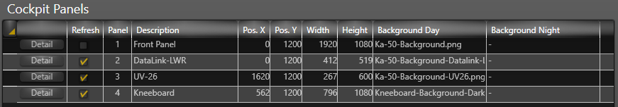
The overview of the "Cockpit Panels" lists the panels for the profile. Here you can create a new panel via the button "Add Record" and delete it after marking an entry by clicking the button "Delete Record".
The list of "Cockpit Panels" includes the following columns.
Without name: For the button "Detail" for defining a panel.
Refresh: Check this box if the panel is above another and this panel should always be on top.
Panel: Unique ID of the created panels.
Description: The name of the panel, will be displayed later in the detail window.
Pos. X: The horizontal position of the panel, in pixels. The specification refers to all monitors, eg 0 is on the far left of the first Windows monitor.
Pos. Y: The vertical position of the panel, in pixels. The specification refers to all monitors, eg 0 is at the top of the first Windows monitor.
Width / Height: The size (width and height) of the panels in pixels.
Background Day: The name of the image file, for the normal background of the panel.
Background Night: The name of the image file, for the night view background of the panel.
The values in the columns can all be edited later. But this is only for the columns "Pos. X "," Pos.Y "," Width "and" Height "for exact positioning of the panel makes sense.
Clicking on the "Detail" button opens a small subwindow for easy definition of the panel. Here you can make his settings under the following points.
Panel: The unique ID of the panel.
Description: For the description of the panel, the window will be displayed later in the detail
Pos. X / Pos. Y:* The vertical and horizontal position of the panel. The coordinates describe the upper left corner of the panel.
Width / Height: The size (width and height) of the panels, in pixels.
Background Day: The name of the image file, for the normal background of the panel.
Background Night: The name of the image file, for the night view background of the panel.
After clicking on the folder icon, a file dialog opens for selecting the image file. Button Transfer: To apply the settings to the overview.
Attention: The panel background graphics should match the size specified in Width and Height, otherwise the graphic will be cropped or the rest of the panel will be transparent.
Depending on which Log option was activated under Configuration, the "Log" overview contains the recorded data inputs and outputs as well as possible error messages.
This data is needed in case of an error for more detailed analysis. Simply click on the "Copy to clipboard" button and paste the contents of the clipboard into a text document or e-mail.
The button "Refresh" updates the log view.
Attention: The logging should only be activated for a short time in case of an error and for analysis, otherwise large amounts of data can be generated which lead to a high memory load.
If Editor Mode is activated, the additional button "Refresh" will be displayed at the bottom of the Ikarus main window. This button is used to update the cockpit panel view.
The editor mode activates the test slider on the instrument functions tab. This makes it possible to see which input values affect which pointer.
In the editor mode it is possible to position all objects (instruments, switches, lamps and accessories) with the mouse. For this, the object must be clicked with the left mouse button and then moved with the button pressed. In addition, it is possible to resize the object by positioning the mouse over the object and rotating it on the mouse wheel.
For switches and lamps, an orange frame is drawn around the object to make positioning easier for transparent graphics. For switches, one or two red framed areas are additionally drawn, depending on the type. These areas represent the area responsible for the click event, for operating the switch. Care must be taken that the red areas on adjacent switches do not overlap. Otherwise it could be difficult to operate the switch. Switches can only be moved if the mouse clicks within the orange area.
Attention: If objects start to jump around when moving, just zoom in or edit the position above the X and Y values.
To create a new Ikarus profile, proceed as follows.
Click the button "New Profile" on the "Configuration" tab to create a new empty profile. Activate the "Editor Mode"!
A cockpit panel must be created on the same tab. Click on the button "Add Record" and click on the button "Detail" in the list of "Cockpit Panels".
The following data must be specified in the window that opens.
- Description: For the description of the panel, the window will be displayed later in the detail
- Pos. X / Pos. Y: Vertical and horizontal position of the panel, the coordinates describe the upper left corner of the panel.
- Width / Height: The size (width and height) of the panel, in pixels.
- Background Day: Image file for the normal background of the panel.
- Background Night: Image file for the night view Background of the panel. (Optional)
Click on the button "Add Record" on the "Instruments" tab.
For the newly created entry in the list, click on the button "Detail".
The following data must be specified in the window that opens.
- Panel: The panel on which the instrument is to be displayed.
- Class: Select the desired instrument, see the instrument overview.
- Name: For the naming of the instrument. (Optional)
- Pos. X / Pos. Y: The vertical and horizontal position of the instrument on the panel, the coordinates describe the upper left corner of the instrument. (Optional)
- Size: The size, in pixels, in which the instrument should be displayed. (Optional)
- Rotate: The rotation, in degrees, of the instrument. (Optional)
- Image for Frame / Image for Glass: The name of the respective image file. (Optional)
All settings marked Optional can also be made later.
With a click on the "Transfer" button, the settings are transferred to the list.
After clicking on the "Refresh" button, the new instrument will be displayed on the panel.
If you now find that you have selected the wrong instrument, just open the detail window and change the instrument there. Then you have to refresh the view again with the "Refresh" button.
Now you can move the instrument to the desired position with the mouse. Click on the instrument with the left mouse button and keep it pressed.
To resize the instrument, position the pointer over the instrument and rotate the mouse wheel.
You can also change the position, size and rotation of the instrument in the respective columns in the list. The view is updated but only after a click on the "Refresh" button.
The data to be displayed by the instrument is set to the "Instrumentfunctions" tab.
For this purpose, the instrument to be set must first be clicked.
Then a new entry is created on the tab "Instrumentfunctions" by clicking on the button "Add Record".
By moving the slider you can see which instrument function this input value has.
Select the ID of the corresponding function from the export file and enter it in the column "DCS ID".
In the column "ID Fct" you can simply adopt the corresponding description.
Normally you can leave the default values in the input and output column. For some instruments, an input value can be assigned to output values here.
Example: A-10C Variometer (VVI), the instrument has a positive and negative scale with non-linear gradient.
In the A-10C.lua ExportScript the following is noted for this instrument:
[12] = "%.4f", -- Variometer (VVI) {-1.0, -0.5, -0.29, 0.29, 0.5, 1.0} {-6000, -2000, -1000, 1000, 2000, 6000}
We are interested in the information in the curly brackets. The first parenthesis block indicates the input values and the second parenthesis block indicates what should be displayed. The content of the first brackets block can be adopted in the input column and only needs to be extended by a 0 in the middle.
For the output column it gets a little more complicated. Here the test controller must be moved until the pointer is at the corresponding value, e.g. 1000. Then the "Out °" column shows the corresponding angular dimension. This value must be transferred to the Output column. It is important that for each value in the Input column there is a corresponding angle in the Output column.
Finally, the following should be in the input and output column.
Input: -1.0, -0.5, -0.29, 0, 0.29, 0.5, 1.0 Output: -170, -85, -50, 0, 50, 85, 170
The number of values in the input and output column must always match.
If the corresponding values do not exist in the ExportScript file, please refer to the mainpanel_ini.lua file of the module.
The following example for the VVI of the A-10C:
 Variometer = CreateGauge ()
 Variometer.arg_number = 12
 Variometer.input = { - 6000 , - 2000 , - 1000 , 1000 , 2000 , 6000 }
 Variometer.output = { - 1.0 , - 0.5 , - 0.29 , 0.29 , 0.5 , 1.0 }
 Variometer.controller = controllers.  variometers
Attention: There are only a few instruments where the values in the Input/Output column can be changed. These instruments already have the corresponding information in the profiles supplied.
Attention: If the instrument is a display or a monitor, the tick must be set in the "Asci" column. This will not change the value sent to Ikarus.
In the input column, a color value can be specified in the form of a HEX value, eg 95E295 for a light green.
In the Output column, the number of displayed characters must be specified for a display, eg 8. For a monitor, in addition to the number of characters displayed, the number of lines is specified, eg 24.10.
The text color and the number of characters / lines must only be entered in the first line of the instrument function.
Each line contains the corresponding DCS ID, including the first one.
Click on the button "Add Record" on the tab "Switch".
For the newly created entry in the list, click on the button "Detail".
The following data must be specified in the window that opens.
- Panel: Selection of the panel on which the switch is to be displayed.
- Class name: Selection of the appropriate type of switch.
- List without name: Selection of the switch function and ID, the list depends on the previously selected Switch Class.
- Image ON: Name of the image file that represents the ON position of the switch or the handle of the knob.
- Image OFF: Name of the image file that represents the OFF position of a simple switch or the center of an on-off-on switch. (Optional or empty)
- Image ON: Name of the image file that represents the second ON position of the on-off-on switch. (Optional or empty)
- Pos. X / Pos. Y: Vertical and horizontal position of the switch on the panel, the coordinates describe the upper left corner of the switch. (Optional)
- Size: The size (width), in pixels, in which the switch should be displayed. (Optional)
All settings marked Optional can also be made later.
With a click on the "Transfer" button, the settings are transferred to the list.
After clicking on the "Refresh" button, the new switch is displayed on the panel.
If you have made a mistake, open the detail window again and correct the settings. After a further "refresh" the changes are displayed.
The position, size and rotation of the switch can be changed as described under Instruments.
The red buttons of different switches should not overlap, otherwise the switches can not be clearly operated.
Click on the button "Add Record" on the tab "Lamps".
For the newly created entry in the list, click on the button "Detail".
The following data must be specified in the window that opens.
- Panel: Selection of the panel on which the lamp is to be displayed.
- List without name: Selection of the lamp function and ID.
- Image ON: The name of the image file representing the on mode.
- Image OFF: The name of the image file that represents the Off mode.
- Pos. X / Pos. Y: The vertical and horizontal position of the lamp on the panel, the coordinates describe the upper left corner of the lamp. (Optional)
- Size: The size (width), in pixels, in which the lamp is to be displayed. (Optional)
All settings marked Optional can also be made later.
With a click on the "Transfer" button, the settings are transferred to the list.
After a click on the "Refresh" button, the new lamp will be displayed on the panel.
If you have made a mistake, open the detail window again and correct the settings. After a further "refresh" the changes are displayed.
The position, size and rotation of the lamp can be changed as described under Instruments.
Click on the button "Add Record" on the tab "Accessories".
For the newly created entry in the list, click on the button "Detail".
The following data must be specified in the window that opens.
- Panel: Selection of the panel on which the accessory should be displayed.
- Image: The name of the image file.
- Pos. X / Pos. Y: The vertical and horizontal position of the accessory on the panel. The coordinates describe the upper left corner of the lamp. (Optional)
- Size: The size (width), in pixels, in which the accessory should be displayed. (Optional)
All settings marked Optional can also be made later.
With a click on the "Transfer" button, the settings are transferred to the list.
After clicking on the "Refresh" button, the new accessory is displayed on the panel.
If you have made a mistake, open the detail window again and correct the settings. After a further "refresh" the changes are displayed.
The position, size and rotation of the accessory can be changed as described under Instruments.
With existing profiles, you can change everything, whether it's the position, size and number of panels, or other objects, such as the instruments, switches, lights and accessories, or just the graphics.
All graphics for the backgrounds, frames, instrument glasses, switches, lamps and accessories should be saved in PNG format, as only this format offers reasonable support for transparency. The color depth used should be 8bit or 32bit.
Graphics for switches must always be created in such a way that the base of the switch coincides in all positions. With a toggle switch, for example, the base must always be in the middle.

For rotary encoders (Rotarys) and rotary switches (MultiSwiches) only one graphic is needed, as the graphic is only rotated here. Therefore, it is important that the graphic is square and the center of the knob is in the middle of the graphic.
Under Windows, monitors can be positioned differently. This then has a corresponding effect on the settings in Ikarus.
Here are two examples:
Two monitors next to each other, with the monitor number 1 intended for the game.


Windows screen settings

All panels are now displayed on Monitor 2 (Pos. X).
Two monitors with each other, with the monitor number 1 is intended for the game.


Windows screen settings
All panels are now displayed on Monitor 2 (Pos. Y).