The dynamics and kinematics of a drone are crucial in understanding and controlling its flight behavior. The drone's state can be described by its position (x, y, z), orientation (roll ( \phi ), pitch ( \theta ), and yaw ( \psi )), and their respective velocities and angular velocities.
The translational motion of the drone can be described by Newton's second law of motion:
[ m\ddot{\mathbf{r}} = \mathbf{F} - mg\hat{z} ]
where:
- ( m ) is the mass of the drone.
- ( \ddot{\mathbf{r}} ) represents the linear acceleration.
- ( \mathbf{F} ) is the total thrust force generated by the drone's motors.
- ( g ) is the acceleration due to gravity.
- ( \hat{z} ) is the unit vector in the vertical direction.
The rotational motion of the drone is described using Euler's equations of motion for a rigid body:
[ I \dot{\boldsymbol{\omega}} + \boldsymbol{\omega} \times (I \boldsymbol{\omega}) = \mathbf{\tau} ]
where:
- ( I ) represents the moment of inertia matrix.
- ( \boldsymbol{\omega} ) is the angular velocity vector (p, q, r).
- ( \mathbf{\tau} ) is the vector of external torques acting on the drone.
The dynamics of the drone can be represented in a state-space format, where the state vector ( \mathbf{x} ) might include the position, velocity, orientation, and angular velocity. The state-space model is typically written as:
[ \dot{\mathbf{x}} = A\mathbf{x} + B\mathbf{u} ] [ \mathbf{y} = C\mathbf{x} + D\mathbf{u} ]
Where:
- ( \mathbf{x} ) is the state vector.
- ( \mathbf{u} ) is the input vector (like motor thrusts).
- ( \mathbf{y} ) is the output vector (like measured position and orientation).
- ( A ) is the system matrix, representing the dynamics of the drone.
- ( B ) is the input matrix, showing how inputs affect the state.
- ( C ) is the output matrix, linking the state to the outputs.
- ( D ) is the direct transmission matrix, usually a zero matrix in drone dynamics.
The matrices ( A ), ( B ), ( C ), and ( D ) are determined based on the physical characteristics of the drone and its operational environment. They encapsulate the dynamics and kinematics, converting control inputs into predictions about the drone's future state.
The control inputs for the drone include thrust ( U1 ) and torques ( U2, U3, U4 ). These inputs are calculated as follows:
[ U1 = c_t(\omega_1^2 + \omega_2^2 + \omega_3^2 + \omega_4^2) ] [ U2 = c_t l (\omega_2^2 - \omega_4^2) ] [ U3 = c_t l (\omega_3^2 - \omega_1^2) ] [ U4 = c_q (-\omega_1^2 + \omega_2^2 - \omega_3^2 + \omega_4^2) ]
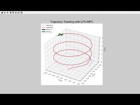
The desired trajectory is represented as a function of time ( t ):
[ X_{ref}(t), Y_{ref}(t), Z_{ref}(t), \psi_{ref}(t) ]
LPV systems are described by the following equations:
[ \dot{x}(t) = A(t)x(t) + B(t)u(t) ] [ y(t) = C(t)x(t) + D(t)u(t) ]
Model Predictive Control (MPC) is an advanced method of process control that uses a dynamic model to predict and optimize future states of a control system. In the context of drone trajectory tracking, MPC is used to compute the optimal control inputs that will guide the drone along a desired trajectory. The basic formulation of an MPC problem can be given as follows:
[ \min_{u} \sum_{k=0}^{N-1} \left( (x_k - x_{ref})^T Q (x_k - x_{ref}) + (u_k - u_{ref})^T R (u_k - u_{ref}) \right) ]
Subject to the dynamic constraints of the system:
[ x_{k+1} = A x_k + B u_k ] [ x_{min} \leq x_k \leq x_{max} ] [ u_{min} \leq u_k \leq u_{max} ]
Where:
- ( x_k ) is the state of the system at step ( k ).
- ( u_k ) is the control input at step ( k ).
- ( x_{ref} ) and ( u_{ref} ) are the reference state and input, respectively.
- ( Q ) and ( R ) are weighting matrices.
- ( N ) is the prediction horizon.
- ( A ) and ( B ) are the system matrices.
- ( x_{min}, x_{max}, u_{min}, u_{max} ) are the bounds on states and inputs.