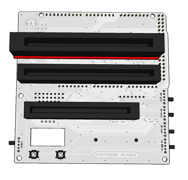
How to build the PCB
-1) Start by flashing the latest Cart Reader code to the Arduino like shown here.
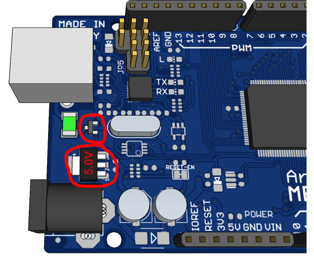
1) Now desolder the transistor and the 5V voltage regulator from the Arduino board. Don't skip this step, it's important.
These two parts need to be removed so that the Cart Reader can switch the Arduino between 5V and 3.3V. On the Robotdyn Arduino the transistor is located a little bit further to the right just below the CH340 chip, like shown in the video. For the official Arduino Mega follow this picture.
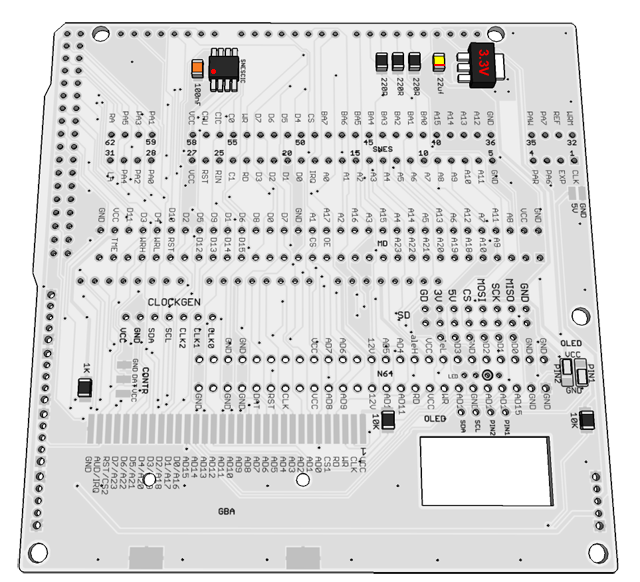
Be careful the 22uF tantalum capacitor(positive side is marked with a line and faces the 22uF marking on the PCB) and the PIC microcontroller(the dot on the chip lines up with the notch on PCB) have to be soldered in a certain orientation. The PIC also has to be flashed with the snesCIC code before you solder it to the PCB. The AMS1117-3.3 voltage regulator here needs to be 3.3V so you can't re-use the 5.0V one you de-soldered earlier. The 100nF capacitor and the resistors are not polarized and can be soldered in any orientation.
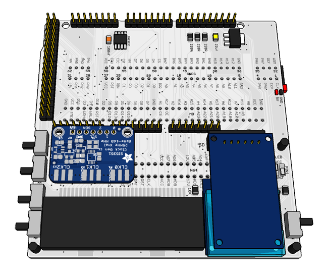
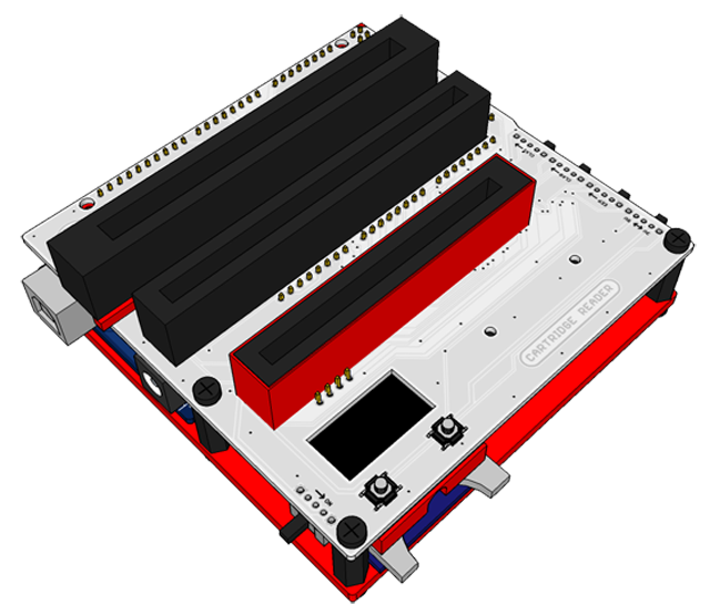
3) Solder the GBA slot, the switches, the male pin-headers and the female pin-headers for the clock generator and for the mSD and/or full-size SD module.
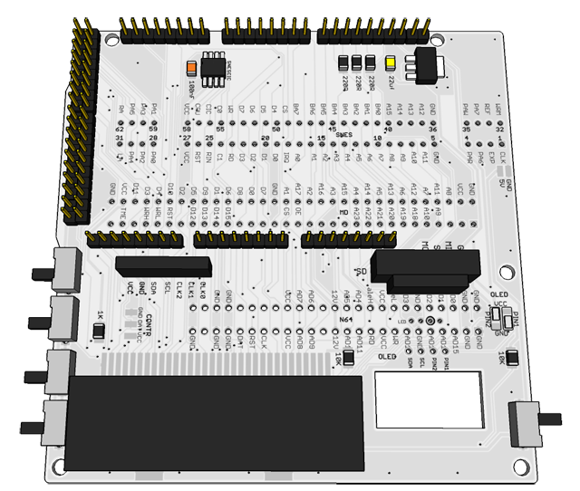
4) Place the SNES spacer underneath the SNES slot and solder it together with the Mega Drive slot and N64 slot. Next solder the two pushbuttons.
The SNES spacer raises the SNES slot a little so that you don't have to trim the pins of the SNES slot, but it's optional.
Be careful not to short the pins of the buttons to the metal casing, which can easily happen if you use too much solder.
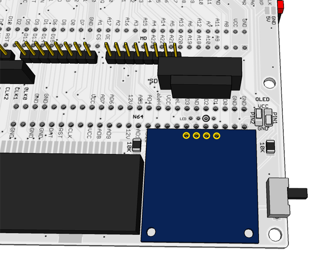
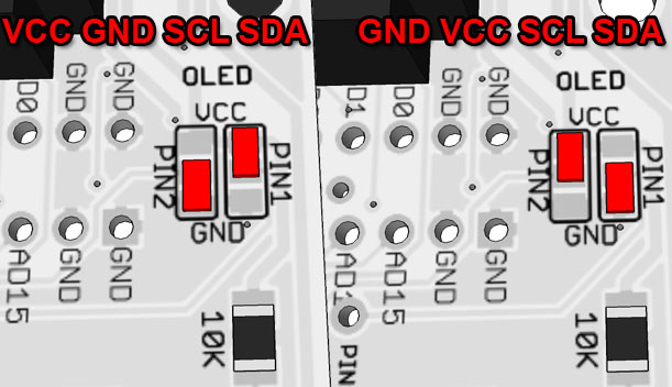
5) Solder OLED and configure the two OLED solder jumpers depending on whether pin 1 of the OLED is GND or VCC.
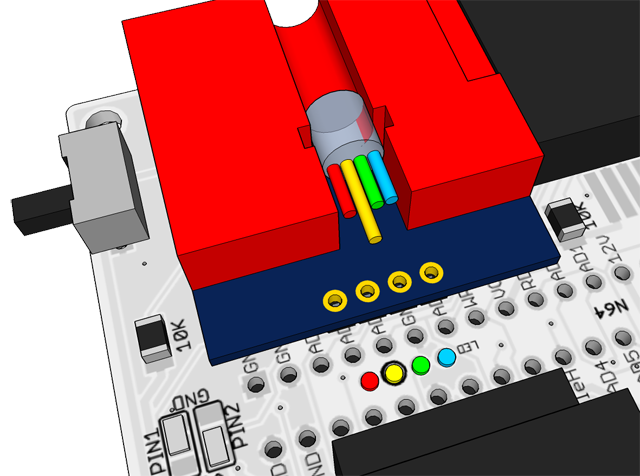
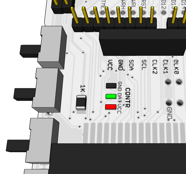
6) Install the SD spacer using some double-sided sticky tape or hot glue and solder the legs of the LED as shown, be careful not to short anything.
Red, green and blue are negative pins. The longer leg of the LED is positive. The positive pin is marked on the PCB with a circle around the hole.
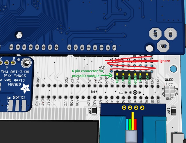
You have to either desolder or bend and trim the pins of the microSD module before plugging it into the 6-pin connector.
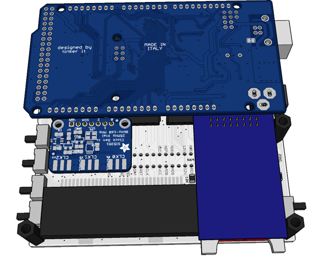
Be sure to solder the pin header to the Clock Generator the right way, the 0, 1, 2 etc. markings on the clock gen PCB need to align with the CLK0, CLK1, CLK2 print on the Cart Reader PCB.
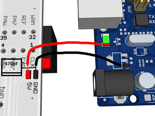
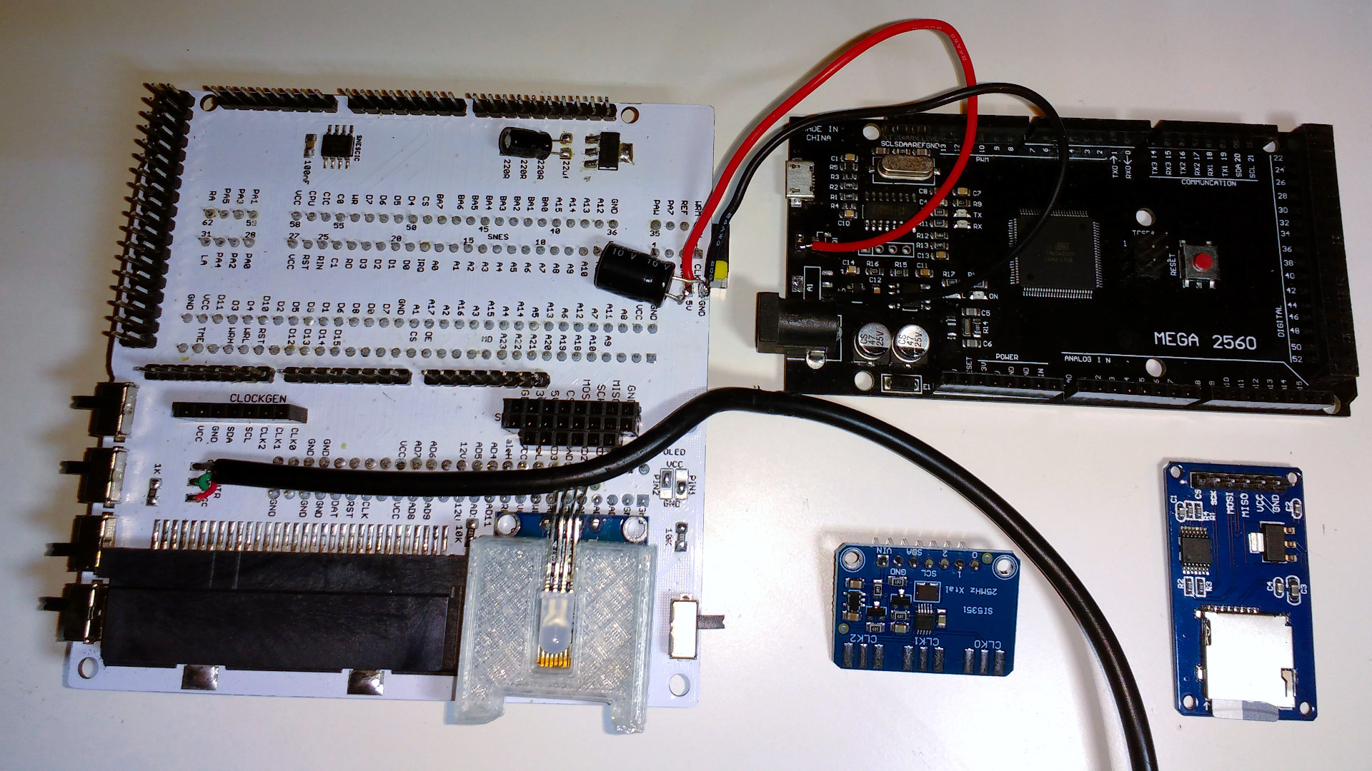
Because we de-soldered the two parts from the Arduino earlier we now need to create a new path for the supply voltage. Connect a wire from the GND pad of the Cart Reader shield to any GND point on the Arduino board and a second wire from the 5V pad to the point right after the green fuse.
In the video I add a 47uF capacitor here but a bigger 470uF soldered sideways is strongly recommended for SNES SA-1 carts. You can desolder the barrel plug connector if you need more space for the capacitor.