This repository presents the mixed signal design of a SAR ADC. The Digital part of the circuit i.e SAR block and control block is simulated on Makerchip tool. All the Simulations are done using Esim and Makerchip tool only. Since the counter used is taken to be 8-Bit, the input voltage that can be converted to analog is limited to 0-3.3V. A 8-Bit Digital to Analog Converter (DAC) is used as an internal part, having the step size of 12.89mV.
- Introduction
- Tool Used
- Reference Circuit Diagram
- Expected Waveform
- Approach
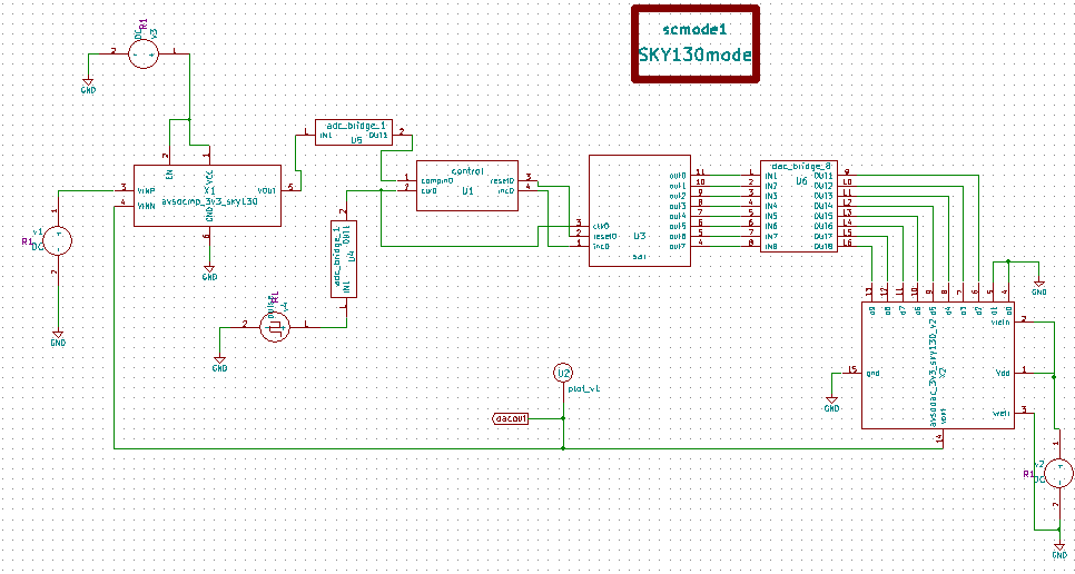
- Schematic
- Verilog Code of SAR Block
- Verilog Code of Control Block
- Waveforms
- Generated Netlist
- Result
- Generation of Digital Block Model using Ngveri Tab
- Steps to Run Simulation of Project
- Reference
- Acknowledgement
- Author
The world surrounding us has only analog signals which were utilised and analysed by the engineers before the digital era. In the digital era all the signals are digital in nature and hence the usage of analog to digital converters(adc's) has increased significantly. Digital domain provides the facilities of higher speeds, storage, high immunity to noise and what not. In order to have maximum benefits we need are adc's to be fast and efficient. SAR type adc is one of the fastest adc which can be designed. An SAR(Successive Approximation Register) block take only number of pulses equal to the number of bits. Where adc like counter type counts to 2 power N times, an SAR block does that in N pulses only.
eSim (previously known as Oscad / FreeEDA) is a free/libre and open source EDA tool for circuit design, simulation, analysis and PCB design. It is an integrated tool built using free/libre and open source software such as KiCad, Ngspice, Verilator, makerchip-app, sandpiper-saas and GHDL. eSim is released under GPL.
eSim offers similar capabilities and ease of use as any equivalent proprietary software for schematic creation, simulation and PCB design, without having to pay a huge amount of money to procure licenses. Hence it can be an affordable alternative to educational institutions and SMEs. It can serve as an alternative to commercially available/licensed software tools like OrCAD, Xpedition and HSPICE.
For more details refer: https://esim.fossee.in/home
NgSpice is the open source spice simulator for electric and electronic circuits. Such a circuit may comprise of JFETs, bipolar and MOS transistors, passive elements like R, L, or C, diodes, transmission lines and other devices, all interconnected in a netlist. Digital circuits are simulated as well, event driven and fast, from single gates to complex circuits. And you may enter the combination of both analog and digital as a mixed-signal circuit.
For more details refer: http://ngspice.sourceforge.net/docs.html
It is an Online Web Browser IDE for Verilog/System-verilog/TL-Verilog Simulation.
For More Details Refer: https://www.makerchip.com/
It is a tool which converts Verilog code to C++ objects.
For More Details Refer: https://www.veripool.org/verilator/
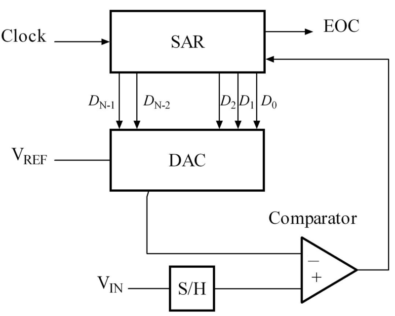
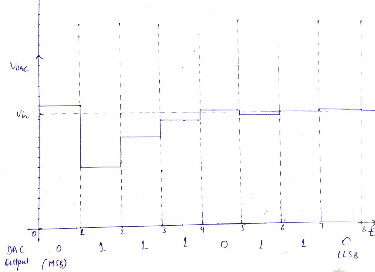
The analog input voltage (VIN) is held constant. To implement the binary search algorithm, the N-bit register is first set to midscale (that is, 100... .00, where the MSB is set to 1). This forces the DAC output (VDAC) to be VREF/2, where VREF is the reference voltage provided to the ADC. A comparison is then performed to determine if VIN is less than, or greater than, VDAC. If VIN is greater than VDAC, the comparator output is a logic high, or 1, and the MSB of the N-bit register remains at 1. Conversely, if VIN is less than VDAC, the comparator output is a logic low and the MSB of the register is cleared to logic 0. The SAR control logic then moves to the next bit down, forces that bit high, and does another comparison. The sequence continues all the way down to the LSB. Once this is done, the conversion is complete and the N-bit digital word is available in the register.
module sar( output reg [7:0]out,input inc,reset, clk);
reg [2:0] ca,cb;
always @(ca)begin
if(ca !=0 )cb <= ca - 3'd1;
end
initial begin
ca <= 3'd7;
out <= 8'd128;
end
always @(reset)begin
ca <= 3'd7;
out <= 8'd128;
end
always @(negedge clk) begin
if(ca != 0)ca <= ca - 3'd1;
end
always @(posedge clk) begin
 if((cb+1)!=0) begin
 out[cb] <= 1'b1;
 end
 out[ca] <= inc;
end
endmodule
module control(output reset, inc, input compin,clk);
assign inc = compin;
reg [3:0] count;
reg res;
initial begin
count = 4'b0;
end
DFF d0(reset,res,clk);
always @(count[3])begin
res = 1'b1;
count = 4'b0;
end
always @(reset) begin
res = 1'b0;
end
always @(posedge clk) begin
count = count + 4'd1;
end
endmodule
module DFF(output reg Q, input D,clk);
always @(posedge clk) begin
Q <= D;
end
endmodule
- Vin = 0.9

- Vin = 1.2

- Vin = 2.4

* c:\users\hp\esim-workspace\sar8bit\sar8bit.cir
.include avsddac_3v3_sky130_v2.sub
.include rropamp31.sub
.include "D:\FOSSEE\eSim\library\sky130_fd_pr\models\sky130_fd_pr__model__diode_pd2nw_11v0.model.spice"
.include "D:\FOSSEE\eSim\library\sky130_fd_pr\models\sky130_fd_pr__model__pnp.model.spice"
.include "D:\FOSSEE\eSim\library\sky130_fd_pr\models\sky130_fd_pr__model__diode_pw2nd_11v0.model.spice"
.lib "D:\FOSSEE\eSim\library\sky130_fd_pr\models\sky130.lib.spice" tt
.include "D:\FOSSEE\eSim\library\sky130_fd_pr\models\sky130_fd_pr__model__linear.model.spice"
.include "D:\FOSSEE\eSim\library\sky130_fd_pr\models\sky130_fd_pr__model__r+c.model.spice"
.include "D:\FOSSEE\eSim\library\sky130_fd_pr\models\sky130_fd_pr__model__inductors.model.spice"
* u3  net-_u1-pad4_ net-_u1-pad3_ net-_u1-pad2_ net-_u3-pad4_ net-_u3-pad5_ net-_u3-pad6_ net-_u3-pad7_ net-_u3-pad8_ net-_u3-pad9_ net-_u3-pad10_ net-_u3-pad11_ sar
v1 net-_x1-pad4_ gnd  dc 1.2
x2 net-_x2-pad1_ net-_x2-pad1_ gnd gnd gnd net-_u6-pad9_ net-_u6-pad10_ net-_u6-pad11_ net-_u6-pad12_ net-_u6-pad13_ net-_u6-pad14_ net-_u6-pad15_ net-_u6-pad16_ dacout gnd avsddac_3v3_sky130_v2
* s c m o d e
* u5  comp net-_u1-pad1_ adc_bridge_1
* u6  net-_u3-pad11_ net-_u3-pad10_ net-_u3-pad9_ net-_u3-pad8_ net-_u3-pad7_ net-_u3-pad6_ net-_u3-pad5_ net-_u3-pad4_ net-_u6-pad9_ net-_u6-pad10_ net-_u6-pad11_ net-_u6-pad12_ net-_u6-pad13_ net-_u6-pad14_ net-_u6-pad15_ net-_u6-pad16_ dac_bridge_8
v4  net-_u4-pad1_ gnd pulse(1.8 0 0 0 0 0.5m 1m)
* u4  net-_u4-pad1_ net-_u1-pad2_ adc_bridge_1
v2 net-_x2-pad1_ gnd  dc 3.3
* u2  dacout plot_v1
v3 net-_x1-pad1_ gnd  dc 3.3
x1 net-_x1-pad1_ gnd dacout net-_x1-pad4_ comp rropamp31
* u7  comp plot_v1
* u1  net-_u1-pad1_ net-_u1-pad2_ net-_u1-pad3_ net-_u1-pad4_ control
a1 [net-_u1-pad4_ ] [net-_u1-pad3_ ] [net-_u1-pad2_ ] [net-_u3-pad4_ net-_u3-pad5_ net-_u3-pad6_ net-_u3-pad7_ net-_u3-pad8_ net-_u3-pad9_ net-_u3-pad10_ net-_u3-pad11_ ] u3
a2 [comp ] [net-_u1-pad1_ ] u5
a3 [net-_u3-pad11_ net-_u3-pad10_ net-_u3-pad9_ net-_u3-pad8_ net-_u3-pad7_ net-_u3-pad6_ net-_u3-pad5_ net-_u3-pad4_ ] [net-_u6-pad9_ net-_u6-pad10_ net-_u6-pad11_ net-_u6-pad12_ net-_u6-pad13_ net-_u6-pad14_ net-_u6-pad15_ net-_u6-pad16_ ] u6
a4 [net-_u4-pad1_ ] [net-_u1-pad2_ ] u4
a5 [net-_u1-pad1_ ] [net-_u1-pad2_ ] [net-_u1-pad3_ ] [net-_u1-pad4_ ] u1
* Schematic Name:                             sar, NgSpice Name: sar
.model u3 sar(rise_delay=1.0e-9 fall_delay=1.0e-9 input_load=1.0e-12 instance_id=1 )
* Schematic Name:                             adc_bridge_1, NgSpice Name: adc_bridge
.model u5 adc_bridge(in_low=1 in_high=2 rise_delay=1.0e-9 fall_delay=1.0e-9 )
* Schematic Name:                             dac_bridge_8, NgSpice Name: dac_bridge
.model u6 dac_bridge(out_low=0 out_high=3.3 out_undef=0.5 input_load=1.0e-12 t_rise=1.0e-9 t_fall=1.0e-9 )
* Schematic Name:                             adc_bridge_1, NgSpice Name: adc_bridge
.model u4 adc_bridge(in_low=1 in_high=1.5 rise_delay=1.0e-9 fall_delay=1.0e-9 )
* Schematic Name:                             control, NgSpice Name: control
.model u1 control(rise_delay=1.0e-9 fall_delay=1.0e-9 input_load=1.0e-12 instance_id=21 )
.tran 10e-06 10e-03 0e-00

* Control Statements
.control
set color0 = white
set color1 = black
set color2 = red
set xbrushwidth = 2
run
print allv > plot_data_v.txt
print alli > plot_data_i.txt
plot v(dacout)
plot v(comp)
.endc
.end
The Design and simulation of the SAR type ADC is finally done. The ouput has a very small error of around 1% which is quite minimal and in many inputs the output had close 0.1% error. The plots obtained are mathing the excepted waveforms.
- Open eSim
- Run NgVeri-Makerchip
- Add top level verilog file in Makerchip Tab
- Click on NgVeri tab
- Add dependency files
- Click on Run Verilog to NgSpice Converter
- Debug if any errors
- Model created successfully
- Clone this project using the following command:
- To run the project in eSim:
- Run eSim
- Load the project
- Open eeSchema
- Simulate using ngSpice
- Design with operational amplifiers and analog integrated circuits / Sergio Franco, San Francisco State University. – Fourth edition.
- A. Sinha and S. K. Sen, "Design of an improved successive approximation type ADC using multi bit per cycle algorithm for conversion rate improvement.", 2014.
- FOSSEE, IIT Bombay
- Kunal Ghosh, Co-founder, VSD Corp. Pvt. Ltd. - kunalpghosh@gmail.com
- Sumanto Kar, eSim Team, FOSSEE