
ESPi, with its powerful ESP32 and Ethernet, is the ideal answer for your networking requirements. Along with WiFi, this board supports a variety of internet protocols, including TCP, UDP, WOL over UDP, ICMP, IPv4, and others. This repository contains a step-by-step guide for getting started with the ESPi board.
- Powered by ESP32-WROOM-32
- ESP32 Multipurpose GPIO pins breakout for Additional peripheral interfacing
- 1.14" TFT display for visual interaction
- 5-way joystick for adding more control features for project
- SPI, I2C, UART interfacing
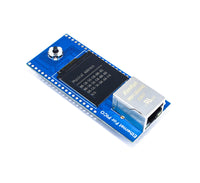
- Onboard RJ45 with Transformer Ethernet Port
- Support 4 independent SOCKETs simultaneously
- Support Hardwired TCP/IP Protocols : TCP, UDP, ICMP, IPv4, ARP, IGMP, PPPoE
- Ethernet power down mode and Wake on LAN over UDP for energy-saving
- 10Base-T/100Base-TX Ethernet PHY with auto-negotiation for full and half duplex with 10 and 100-based connections
- Network indicator LEDs for full/half duplex, link, 10/100 speed, and active status
- Type C interface for programming and powering board
- Status Led for power
- Onboard Boot and reset button
-
ESP32-WROOM-32 is a powerful, generic Wi-Fi + Bluetooth® + Bluetooth LE MCU
-
WiFi 802.11 b/g/n (802.11n up to 150 Mbps) support
-
Bluetooth v4.2 BR/EDR and Bluetooth LE specification
-
Board Supply voltage 5V, GPIO pins operating voltage 3.3V
-
Display Resolution 240x135
-
IPS Display 65K RGB Colors
-
SPI Interface with ST7789 Display Driver
-
Ethernet Network Performance: Max.25Mbps
-
Ethernet TX/RX Buffer : 16KB
-
Operating temperature: -40°C to +85°C

- (1) RJ45 Ethernet
- (2) 1.14” Display
- (3) 5-way Joystick
- (4) ESP32-WROOM-32
- (5) & (9) Multipurpose GPIOs breakout
- (6) Type C
- (7) BOOT Button
- (8) RESET Button
-
Ethernet interfacing with ESP32
ESP32 Ethernet Function GP18 SCLK Clock pin of SPI interface for Ethernet GP23 MOSI/A0 MOSI (Master OUT Slave IN) pin of SPI interface GP19 MISO/A1 MISO (Master IN Slave OUT) pin of SPI interface GP5 CSn Chip Select pin of SPI interface -
Display interfacing with ESP32
ESP32 Display Function GP14 SCK Clock pin of SPI interface for Display GP13 DIN MOSI (Master OUT Slave IN) pin of SPI interface GP15 CS Chip Select pin of SPI interface GP27 DC Data/Command pin of SPI interface GP26 RES Display Reset pin GP4 BL Backlight of display -
Joystick and button interfacing with ESP32
ESP32 Hardware GP25 Joystick Selection/centre GP35 Joystick Down GP32 Joystick Up GP34 Joystick Left GP33 Joystick Right GP0 Boot Button -
Breakout GPIOs
Breakout 1
ESP32 Type* Function GP12 I/O GPIO12, ADC2_CH5, TOUCH5, RTC_GPIO15, MTDI, HSPIQ, HS2_DATA2, SD_DATA2, EMAC_TXD3 GP2 I/O GPIO2, ADC2_CH2, TOUCH2, RTC_GPIO12, HSPIWP, HS2_DATA0, SD_DATA0 GP36 I GPIO36, ADC1_CH0, RTC_GPIO0 GP39 I GPIO39, ADC1_CH3, RTC_GPIO3 GND P Ground pin 3V3 P Positive Supply 3.3V Breakout 2
ESP32/Ethernet Type* Function GP16 I/O GPIO16, HS1_DATA4, U2RXD, EMAC_CLK_OUT GP17 I/O GPIO17, HS1_DATA5, U2TXD, EMAC_CLK_OUT_180 GP22 I/O GPIO22, VSPIWP, U0RTS, EMAC_TXD1 ET_INT - Ethernet Interrupt pin GP21 I/O GPIO21, VSPIHD, EMAC_TX_EN ET_RST - Ethernet Reset pin *I-INPUT, O-OUTPUT, P-POWER & T-HIGH IMPEDENCE
-
Download Arduino IDE from official site and install into your system. We have use Arduino IDE 1.8.19
-
Once installation done will add ESP32-Wroom-32 board support into IDE, for this first you need to add below link into preference:
https://raw.githubusercontent.com/espressif/arduino-esp32/gh-pages/package_esp32_index.jsonSelect File > Preference, and add link as show in below image,

-
Now will install ESP32 based boards as shown in below image,

-
Once done, keeping default settings select the ESP32 Dev Module with suitable com port (may be different in your case) as shown below,

-
In case you don't see com port then you will have to install CP2102 driver from Link. Download and install as per your operating system.
-
check below one recommended for windows user

-
Once installed correctly, it will look like the image below.

-


-
Download library zip file provided here in github.
-
Extract and copy files inside Document > Arduino > Libraries folder. Make sure to restart Arduino IDE whenever you update or add any libraries.


-
At this step you are all set to test codes, for easy getting started we have provided various demo example codes in github which you can download and try.
-
Open one example code in Arduino and make sure you have selected correct board ( ESP32 Dev Module) with suitable com port, click on upload button to transfer code on ESPi.

-
Checkout other examples below and build your own custom program codes using those references.

To compile and run Ethernet server codes without getting compile Error , You will have to replace default "Server.h" file comes when ESP32 board installed in Arduino, location is shown below
C:\Users\YourUserName\AppData\Local\Arduino15\packages\esp32\hardware\esp32\2.0.9\cores\esp32
Replace with file "Server.h" provided here in github.

The examples folder in repository includes ready to use and experimental code with ESPi, some listed below ->
- Example 1 : Display demo code
- Example 2 : WiFi Webserver application demo
- Example 3 : Combine test of EthernetWebServer and WiFiWebServer on ESPi board
- Example 4 : Application demo code to connect ESPi board with ThingSpeak cloud server using onboard ethernet facility
Play with it and create your own, Happy Coding!
- ESPi Schematic
- Product Hardware Files
- Product Step File
- Getting Started with ESP32 in Arduino
- Arduino IDE 1 overview
- ESP32 Wroom 32 Datasheet
- Wiznet Datasheet
- Wiznet References
-
NetPi : HAT with onBoard Ethernet support can be powered by Raspberry Pi Pico / Pico W
-
Touchsy : 3.2" Touch LCD Display Based on ESP32 MCU
-
Ardi-32 : Uno R3 Alternative Board Based on ESP32-S3-WROOM-1

This is open source product. Kindly check the LICENSE.md file for more information.
Please contact support@sb-components.co.uk for technical support.