
This Github provides a getting started guide and other working details for the Pico Cell 4G.
- Powered by RP2040 chip, featuring a 32-bit dual ARM Cortex-M0+ microcontroller with 8MB Flash.
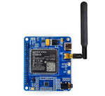
- Equipped with Quectel EG25-G 4G LTE cellular module for seamless connectivity.
- SIM card holder to support nano SIM.
- Dual Type C interface for Programming Chip and to access the 4G module standalone.
- 3.2” Touch Display with a resolution of 320x240 pixels, driven by the ILI934 Display Driver and FT6236 capacitive touch controller.
- Appearance: RGB, Colors: 65K/262K, offering vibrant visuals.
- Additional GPIO breakouts for interfacing other peripherals, enhancing versatility.
- Boot buttons for easy Pico programming.
- PWR Button for manual 4G module ON/OFF control.
- The onboard buzzer provides audible alerts and notifications for an enhanced user experience.
- Onboard microSD card for data logging purposes.
- Battery connector with charging circuit for portable use cases.
- 3.5mm Audio Jack support to allow the use of headphones.
- Speaker support is also available for attaching a speaker.
- Indicator LEDs for Board supply, Module Power, Network, and Status, keeping you informed.

| (1) 3.2” Touch Display | (2) Type C 4G module AT command | (3) NET_MODE LED |
| (4) NET_STATUS LED | (5) Network Light LED | (6) GPIOs Breakout |
| (7) Module Power Button | (8) Boot Button | (9) Type C RP2040 Programming |
| (10) Display FPC connector | (11) Buzzer | (12) Speaker 2.54” header 2 pin |
| (13) 3.5mm Audio Jack | (14) Micro SDcard slot | (15) Nano Sim slot |
| (16) Charging LED | (17) Battery Connector | (18) Quectel EG25-G Module |
| (19) Auxiliary Antenna uFL connector | (20) GPS Antenna uFL connector | (21) Main Antenna SMA connector |
| (22) Power LED |
-
Pico and 4G Module interfacing
Pico 4G Module Function GP0 (TXD0) RXD UART Communication Pin GP1 (RXD0) TXD UART Communication Pin GP22 PowerKey Module Power Key GP20 Reset Module Reset Pin -
Pico and Touch I2C interfacing
Pico Touch Controller Function GP6 SDA Touch I2C GP7 SCL Touch I2C GP13 RST Touch Reset GP14 IRQ Touch Intrrupt -
Pico and Display SPI interfacing
Pico Display Pin Function GP10 SCLK Clock pin of SPI interface for display GP11 DIN MOSI (Master OUT Slave IN) data pin of SPI interface GP8 DC Data/Command pin of SPI interface GP9 CS Chip Select pin of SPI interface for display GP13 Reset Display Reset Pin GP21 BL Display backlight Pin -
Pico and micro SD card SPI interfacing
Pico microSD Card Function GP2 SCLK Clock pin of SPI interface for microSD card GP3 DIN MOSI (Master OUT Slave IN) data pin of SPI interface GP4 DOUT MISO (Master IN Slave OUT) data pin of SPI interface GP5 CS Chip Select pin of SPI interface for SDcard -
Buzzer Interfacing with Pico
Pico Buzzer Function GP15 +Ve Pin PWM control pin -
GPIOs Breakout

Pico Function GP27 GPIO/ADC1/SCL1/PWM5B GP26 GPIO/ADC0/SDA1/PWM5A GP18 GPIO/SDA1/SCLK0/PWM1A GP17 GPIO/SCL0/CS0/RXD0/PWM0B GP16 GPIO/SDA0/MISO0/TXD0/PWM0A VCC USB_5V/Battery_IN 3.3V Positive 3.3V supply GND Supply ground pin

-
Mostly, Pico Cell 4G will be provided with firmware pre-installed, so you can skip this step if firmware is already present and directly jump start programming by following the below Step 2.
-
In this case, you want to add MicroPython firmware in device. First, you need to Press and Hold the BOOT button, and then, without releasing the button, connect it to PC/laptop using Type C cable. You have to use RP2040 USB for firmware and coding purpose.
-
Now your device is in boot mode, and you will see a new mass storage device named "RPI-RP2" as shown in the below figure.

-
Download the MicroPython firmware file provided in this repo above as "PicoCell4G_Firmware.uf2" or to download the latest firmware file from the official site, visit here
-
Drag and drop the MicroPython UF2 - "PicoCell4G_Firmware.uf2" file provided in this github onto the RPI-RP2 volume. Reference image shown below how to transfer any UF2 file or you can copy paste as well. Device will reboot and you are now running MicroPython on device.


-
Download Thonny IDE from Download link as per your OS and install it.
-
Once done start Thonny IDE application, Connect Pico Cell 4G to laptop/PC.
-
Select device at the bottom right with a suitable COM port, as shown in the below figure. You might get a different COM port.
-
Write simple Python code or Copy Demo Buzzer, then click on the green run button to make your script run on device.

Now that we've reached this point, you're executing your script through Thonny IDE, so if you unplug Pico Cell 4G, it will stop running. To run your script without using an IDE, simply power up device and it should run your script, go to step 3.

-
Click on File -> Save Copy -> select Raspberry Pi Pico , Then save file as main.py

In similar way you can add various python code files to Pico Cell 4G. Also you can try out sample codes given here in examples folder.
-
But in case if you want to move multiple files at one go, example suppose you are interested to save library files folder, below image demonstrate that

Save whatever example code file you want to try as main.py and make sure you have added lib and fonts folder. In example folder you will find demo example script code to test onboard components of Pico Cell 4G like
- Display Demo : code to test touch display
- SD card Demo : code to test micro SD card basic operations
- 4G Module Demo : This demonstrates Call, SMS and GPS features.
Using this sample code as a guide, you can modify, build, and share codes!!
-
You can use the Quectel EG25-G standalone to connect to the internet and test various functionalities by sending AT instructions. Simply connect Pico Cell 4G to PC/laptop via 4G USB Type C.
-
Now press, hold Power Key button and release after 3-4 seconds to activate module. LEDs associated with the network will light up, first NET_STATUS then NET_MODE will be on and finally NetLight LED starts blinking. This confirms module ready for use.
-
To verify open device Manager and check if below listing you can see into COM port. If you cannot see device then driver is missing, download and install driver from here

-
If everything goes well it will connect as a cellular network in your system as shown below. After the succesfull 4G Module connection you will able to use your cellular network to connect with internet.

-
Visit the Link to checkout AT COMMAND Testing procedure.

- Schematic
- Hardware Files
- 3D Casing File
- Quectel EG25-G Module Datasheet
- EG25-G Module Command Manual
This is open source product. Kindly check LICENSE.md file for more information.
Please contact support@sb-components.co.uk for technical support.