This Github provides a getting started guide for Quectel EG25-G Module Breakout.
- LTE Cat 4 module optimized for M2M and IoT applications
- Worldwide LTE, UMTS/HSPA(+) and GSM/GPRS/EDGE coverage
- Multi-constellation GNSS receiver available for applications requiring fast and accurate fixes in any environment
- Feature refinements: supports DFOTA and DTMF
- MIMO technology meets demands for data rate and link reliability in modem wireless communication systems
- LTE Cat 4 Max. 150 Mbps (DL) Max. 50 Mbps (UL)
- Max. 42 Mbps (DL) Max. 5.76 Mbps (UL)
- LGA Package
- Wi-Fi Interface
- Bluetooth Interface
- USB 2.0 High-Speed Interface
- Embedded Abundant Protocols
- Multi-constellation GNSS
- Quectel Enhanced AT Commands
- USB Drivers

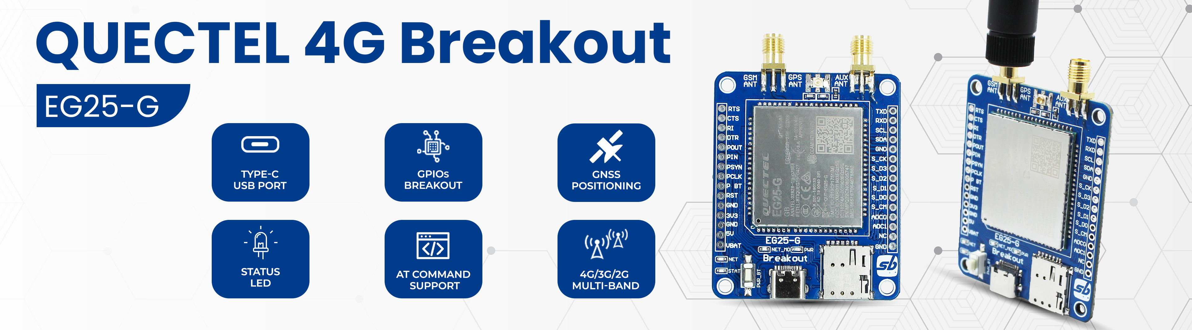
| (1) Auxiliary Antenna SMA connector | (2) Main Antenna SMA connector | (3) Quectel EG25-G Module |
| (4) nano SIM slot | (5) Type C interface | (6) Module Power BTN |
| (7) NET_STATUS LED | (8) Network LED | (9) NET_MODE LED |
| (10) Power LED | (11) GPS Antenna uFL connector | (12) GPIOs and Power Breakout |
-
Simply connect breakout to PC/laptop via USB Type C.
-
Now press, hold Power Key button and release after 3-4 seconds to activate module. LEDs associated with the network will light up, first NET_STATUS then NET_MODE will be on and finally NetLight LED starts blinking. This confirms module ready for use.
-
To verify open device Manager and check if below listing you can see into COM port. If you cannot see device then driver is missing, download and install driver from here

-
If everything goes well it will connect as a cellular network in your system as shown below. After the succesfull 4G Module connection you will able to use your cellular network to connect with internet.


-
Open XCTU software and select the Serial console option to run as shown below.

-
Select Configure option and then suitable AT COM port. Change Baud Rate and other details only if needed, for the 4G module we will keep default settings. Select OK and After that just Close the connection to start.


-
Now the 4G module is ready to accept AT commands for testing. Either you can send commands through console log or create packets to send AT commands.

- AT
- AT+CPIN? You can refer to the manual for more such AT Commands
-
Creating packets is a good option for multiple commands testing. Don’t forget to add 0D and 0A required for carriage return and enter.


-
Pico and Breakout interfacing
Pico 4G Module Function GP0 (TXD0) RXD UART Communication Pin GP1 (RXD0) TXD UART Communication Pin GP22 PowerKey Module Power Key GP20 Reset Module Reset Pin
You follow above connection to interface 4G module breakout with Pico/Pico W. Once done checkout demo example to test Call and SMS features here and make sure to install required E25 library.
- Schematic
- Hardware Files
- 3D Step File
- Quectel EG25-G Module Datasheet
- EG25-G Module Command Manual
- EG25-G Driver
This is open source product. Kindly check LICENSE.md file for more information.
Please contact support@sb-components.co.uk for technical support.