
ScanGenie is your powerful barcode solution with a 1.14" LCD screen, rapid Barcode/QR code scanner, versatile UART communication, Type-C USB port, and a buzzer. It simplifies complex barcode decoding, effortlessly connects to the cloud, and provides real-time feedback. Supporting 20 barcode symbologies, it's an open-source platform for developers and enthusiasts. Say goodbye to tough barcode challenges with ScanGenie's simplicity and versatility.
This GitHub page offers a step-by-step tutorial for using ScanGenie.
- Powered with ESP32 makes it IoT enabled device to connect internet Cloud using WiFi and BLE for local wireless transmission
- 1.14" TFT display for visual interaction
- Read all mainstream 1D 2D barcodes in the market easily
- Reads 20 Different Barcode Symbologies, CMOS camera
- Two type C Support :
- for direct Scanner access
- for programming/power
- High brightness, dark environment scanning
- Support multiple systems and languages, secondary development.
- Additional GPIO breakouts for interfacing other peripherals
- Separate Scan button along with Reset and boot buttons for on the go scanning.
- Onboard buzzer provides audible alerts and notifications for enhanced user experience and system feedback.
- Breadboard compatible for easy DIY breadboarding projects
-
ESP32-S3 series of SoCs having Xtensa® dual-core 32-bit LX7 microprocessor, 2.4 GHz Wi-Fi (802.11 b/g/n) and Bluetooth® 5 (LE), Flash up to 16 MB, PSRAM up to 8 MB
-
Board supply voltage: 5V
-
Operating voltage of pins: 3.3V
-
Display resolution 240 × 135 pixels
-
ST7789V2 Display Driver
-
Appearance: RGB, Colors: 65K
-
Reads 20 different symbologies:
- 1D Symbologies-> UPC-A, UPC-E, EAN-8, EAN-13, Code 128, GS1-128, Code 39, Code 93, Code 11, Interleaved 2-of-5, Matrix 2-of-5, Industrial 2-of-5, Codabar, MSI, GS1 DataBar, Datalogic 2-of-5
- 2D Symbologies-> QR Code,Data Matrix, PDF 417, Micro PDF 417,
-
Scanner Resolution: 640*480
-
Communication Mode: USB(USB-KBW, USB-COM),TTL
-
Operating Temperature: -20℃ to 50℃
-
Storage Temperature: -40℃ to 70℃

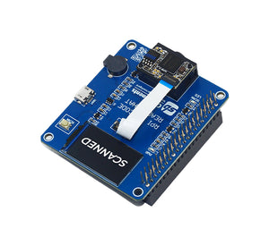
- (1) Barcode DE2120
- (2) Scan Status LED
- (3) Type C for direct Scanner Access
- (4) 1.14” TFT Display
- (5) ESP32 S3 Wroom - 1
- (6) Type C to Program
- (7) Power Status LED
- (8) Battery Charging Indicator
- (9) Reset Button
- (10) Boot Button
- (11) & (13) GPIOs Breakout
- (12) Buzzer
- (14) Scan Button
- (15) Battery Connector
-
Display interfacing with ESP32
ESP32 Display Function IO12 LCD_CLK Clock pin of SPI interface for Display IO11 LCD_DIN MOSI (Master OUT Slave IN) pin of SPI interface IO10 LCD_CS Chip Select pin of SPI interface IO13 LCD_DC Data/Command (MISO) pin of SPI interface IO14 LCD_RST Display Reset pin IO5 BL Backlight of display -
ESP32 and DE2120 Scanner Module interfacing
ESP32 DE2120 Scanner Function IO18 B_RX UART Communication Pin IO17 B_TX UART Communication Pin -
Buttons and Trigger pin
ESP32 Hardware Function IO0 BOOT Boot button IO7 B_SCAN Scan Trigger Pin -
GPIOs Breakout

Breakout 1
ESP32 Type* Multi-Function (Bold-Italic default Function) GP47 I/O/T SPICLK_P_DIFF, GPIO47 , SUBSPICLK_P_DIFF GP21 I/O/T RTC_GPIO21, GPIO21 GP9 I/O/T RTC_GPIO9, GPIO9 , TOUCH9, ADC1_CH8, FSPIHD, SUBSPIHD GP46 I/O/T GPIO46 GP3 I/O/T RTC_GPIO3, GPIO3, TOUCH3, ADC1_CH2 GP20 I/O/T RTC_GPIO20, GPIO20, U1CTS, ADC2_CH9, CLK_OUT1, USB_D+ GP19 I/O/T RTC_GPIO19, GPIO19, U1RTS, ADC2_CH8, CLK_OUT2, USB_D- GP8 I/O/T RTC_GPIO8, GPIO8 , TOUCH8, ADC1_CH7, SUBSPICS1 GP16 I/O/T RTC_GPIO16, GPIO16 , U0CTS, ADC2_CH5, XTAL_32K_N GP15 I/O/T RTC_GPIO15, GPIO15 , U0RTS, ADC2_CH4, XTAL_32K_P GND P Supply Ground GP6 I/O/T RTC_GPIO6, GPIO6 , TOUCH6, ADC1_CH5 GP4 I/O/T RTC_GPIO4, GPIO4 , TOUCH4, ADC1_CH3 3V3 P Positive Supply, 3.3V EN I Enable pin, HIGH - Chip on, LOW - Chip off GND P Supply Ground 3V3 P Positive Supply, 3.3V 5V P Positive Supply, 5V Breakout 2
ESP32 Type* Multi-Function (Bold-Italic default Function) GP43/TXD0 I/O/T U0TXD , GPIO43, CLK_OUT1 GP44/RXD0 I/O/T U0RXD , GPIO44, CLK_OUT2 GP48 I/O/T SPICLK_N_DIFF, GPIO48 , SUBSPICLK_N_DIFF GP45 I/O/T GPIO45 GP35 I/O/T SPIIO6, GPIO35 , FSPID, SUBSPID GP36 I/O/T SPIIO7, GPIO36 , FSPICLK, SUBSPICLK GP37 I/O/T SPIDQS, GPIO37 , FSPIQ, SUBSPIQ GP38 I/O/T GPIO38 , FSPIWP, SUBSPIWP GP39 I/O/T MTCK , GPIO39, CLK_OUT3, SUBSPICS1 GP40 I/O/T MTDO , GPIO40, CLK_OUT2 GND P Ground GP41 I/O/T MTDI , GPIO41, CLK_OUT1 GP42 I/O/T MTMS , GPIO42 GP2 I/O/T RTC_GPIO2, GPIO2, TOUCH2, ADC1_CH1 GP1 I/O/T RTC_GPIO1, GPIO1, TOUCH1, ADC1_CH0 GND P Ground 3V3 P Positive Supply, 3.3V 5V P Positive Supply, 5V *I-INPUT, O-OUTPUT, P-POWER & T-HIGH IMPEDENCE

-
Download Arduino IDE from official site and install into your system. We have use Arduino IDE 1.8.19
-
Once installation done will add ESP32 S3 board support into IDE, for this first you need to add below link into preference:
https://raw.githubusercontent.com/espressif/arduino-esp32/gh-pages/package_esp32_index.jsonSelect File > Preference, and add link as show in below image,

-
Now will install ESP32 based boards as shown in below image,

-
Once done, keeping default settings select the ESP32S3 Dev Module with suitable com port (may be different in your case) as shown below,


-
Download library zip file provided here in github.
-
Extract and copy files inside Document > Arduino > Libraries folder. Make sure to restart Arduino IDE whenever you update or add any libraries.


- At this step you are all set to test codes, for easy getting started we have provided various demo example codes in github which you can download and try.
- Open one example code in Arduino and make sure you have selected correct board with suitable com port, click on upload button to transfer code on ESP32 of Scangenie.

- Checkout other examples below and build your own custom program codes using those references.

For testing any of Scanner code listed in this section your device needs to be in TTL mode, if yes then proceed with example or else follow steps mentioned here in GitHub.
- Example 1 : Display Demo code
- Example 2 : Scanning Barcode/QR Code using Scan Button
- Example 3 : Automatic Scanning Barcode/QR code after regular interval of Time
Now you are ready to try out your own codes, Happy Coding!
-
TTL Mode
TTL mode is default mode in which DE2120 Scanner will work in co-ordination with ESP32 controller of ScanGenie using UART communication. If in case your device mode is different you can follow below steps to get device into TTL mode.
-
First step Scan the below barcode by Pressing onboard Scan button of ScanGenie. This will put device into TTL mode

-
Now to set Baud Rate 9600 by scanning below Barcode, even you can set different Baud Rate by refering Manual provided in this repo.

-
TTL mode is required if you want to try various code example provided in this GitHub repo.
-
-
USB-KBW Mode
You can also use this ScanGenie with USB cable for reading Barcode/Scanner without onboard ESP32 controller board.
-
Connect type C cable to "Barcode" side instead of "PROG" and other end to your laptop/PC.
-
Now simply scan the below Barcode and so this will set board into USB keyboard mode.

-
In USB keyboard mode, you just need to open a notepad/word like application and scan any barcode or QR-code to get their number in your system. As shown in image below

The DE2120 is completely user configurable, you can configure many settings according to your requirement by refering the DE2120 Setting Manual provided in this Repo.
-
- Schematic
- Hardware Files
- Step File
- Getting Started with ESP32 in Arduino
- ESP32 S3 Hardware Reference
- ESP32 S3 Datasheet
- DE2120 Datasheet
- DE2120 Setting Manual
- Arduino IDE 1 overview


This is open source product. Kindly check LICENSE.md file for more information.
Please contact support@sb-components.co.uk for technical support.