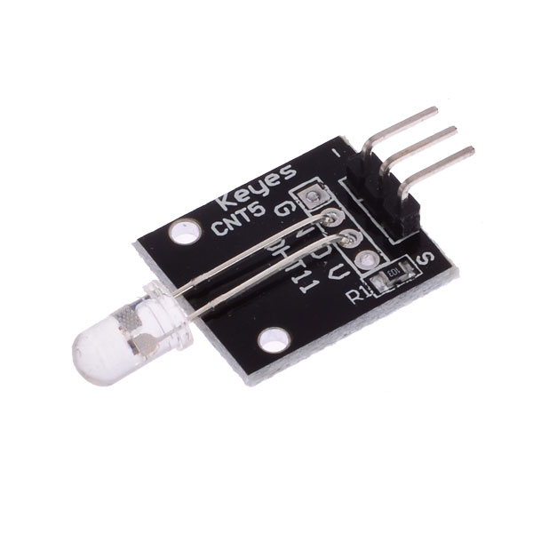
7 color flash
The module contains a 7-color 5mm LED with a built-in chip that sequentially flashes each color in turn. Color pattern is repeated in about 15 seconds.
- LED model: YB-3120B4PNYG-PM
- Forward voltage: 2.5V - 6V
- Forward current: 40mA
| Pin | Description |
|---|---|
| "S" | +5V or +3.3V |
| Central | Ground |
| "-" | Not connected |
Assume LED module is connected to pin D2 of Duinomite board. This corresponds to signal RE2 on pic32 chip.
There are two ways to control GPIO signals from command line: portio utility and text output to /dev/portX device.
First, you need to configure signal RE2 as output:
portio -o e2
Now you can enable (set) the LED:
portio -s e2
To disable (clear) the LED, use:
portio -c e2
It's possible to control GPIO signals via /dev/portX devices.
Configure signal RE2 as output:
echo -------------o-- > /dev/confe
Now you can enable (set) the LED:
echo -------------1-- > /dev/porte
To disable (clear) the LED, use:
echo -------------0-- > /dev/porte
This program enables LED for 15 seconds, then disables it for 3 seconds, in a loop.
#include <stdio.h>
#include <sys/ioctl.h>
#include <sys/gpio.h>

#define MASK_D2     (1 << 2)    /* signal RE2 */

int main()
{
    int fd;
    char *devname = "/dev/porta";

    /* Open GPIO driver. */
    fd = open(devname, 1);
    if (fd < 0) {
        perror(devname);
        return -1;
    }

    /* Configure pin as output. */
    ioctl(fd, GPIO_PORTE | GPIO_CONFOUT, MASK_D2);
    ioctl(fd, GPIO_PORTE | GPIO_CLEAR, MASK_D2);

    for (;;) {
        /* Set D2. */
        ioctl(fd, GPIO_PORTE | GPIO_SET, MASK_D2);
        sleep(15);

        /* Clear D2. */
        ioctl(fd, GPIO_PORTE | GPIO_CLEAR, MASK_D2);
        sleep(3);
    }
    return 0;
}
To compile and run this program, use:
# cc led7.c -o led7
# ./led7