component wiring
The Hardsploit wiring module was created to help you connect your component on our board.
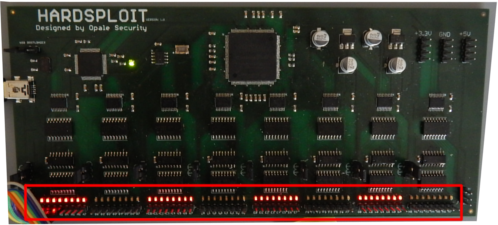
You can find 64 pins corresponding to different signals for different buses. For each pins, an associated led that will turn on when you need to use it.
/!\ You need to connect the Hardsploit board to you computer in order to use the wiring helper
 K2000_STYLE
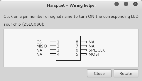
After creating your component, the Wiring module will take the shape of it and the number of pin to draw it, like in a datasheet:
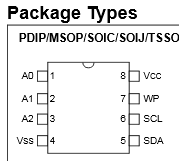
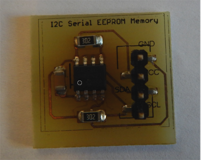
For this example we are working on a 24LC64 I²C Memory. We will not go through the process of desoldering your component (not always needed). We assume it is already prepare to be connected.
The package (datasheet):
The chip:
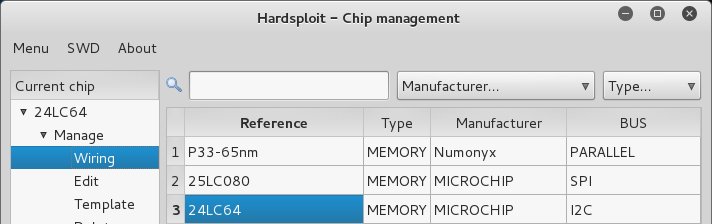
First, we open the Wiring Helper of our component by clicking on the component reference in the main table, then by selecting the "Wiring" option and "Next"
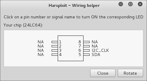
Here is the representation of our component:
Hardsploit wiring helper will not help you found the VCC signals to power your component
Check the power connectivity for more detail
Each signal different to "NA" have a corresponding led / header on the Hardsploit board. By entering the wiring mode, all the led should turned off.
For our component we have 2 pins to connect:
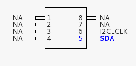
- The clock (I2C_CLK)
- The SDA
Now just click on the signal name / signal number you want to connect and look at the result directly on the Hardsploit board.
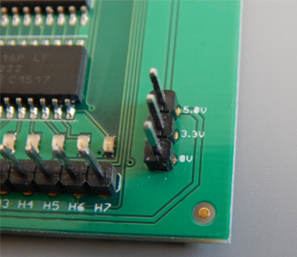
To power your component, you can find headers on both sides of the Hardsploit board.
- Top header -> 5.0V
- Middle header -> 3.3V
- Bottom header -> 0V / GND