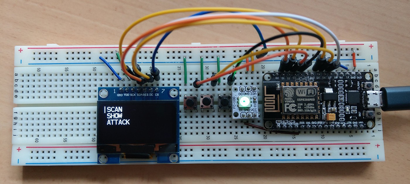
Setup Display & Buttons
Overview:
Using the display interface is completely optional.
The ESP8266 Deauther can also just be used over serial or the web interface.
You should know some basics of how to use, code and create stuff with Arduino.
If you don't, then we highly recommend you to get some sort of Arduino starter kit and start learning. The steps of this tutorial are very simple, but if you have never done something like this, it's very important to get a basic knowledge about the topic first!
I will focus on the NodeMCU in this tutorial since it is the most popular ESP8266 based development board. Every other development board using the ESP8266 should work just like that.
- a breadboard
- jumper wires
- an ESP8266 dev board (i.e. NodeMCU)
- 3 - 6 buttons (3 required, optional up to 6)
- a SSD1306 or SH1106 OLED display with 128x64 pixels
- optional: a RGB LED (3 single LEDs or a neopixel will also work)
- optional but recommended: 2x 10k ohm resistors
- a working Arduino setup that can compile this project (see Installation )
- patience
- common sense
- the ability to read and follow this tutorial carefully
- also recommended: know how to read error messages and use google correctly
For a beginner it's recommended to only use 3 buttons (you can add more later), ab i2c display (those with 4 pins) and (optional) a neopixel as RGB LED.
You can find links to everything you need for this here.
Here is a quick reference of the NodeMCU pinout:
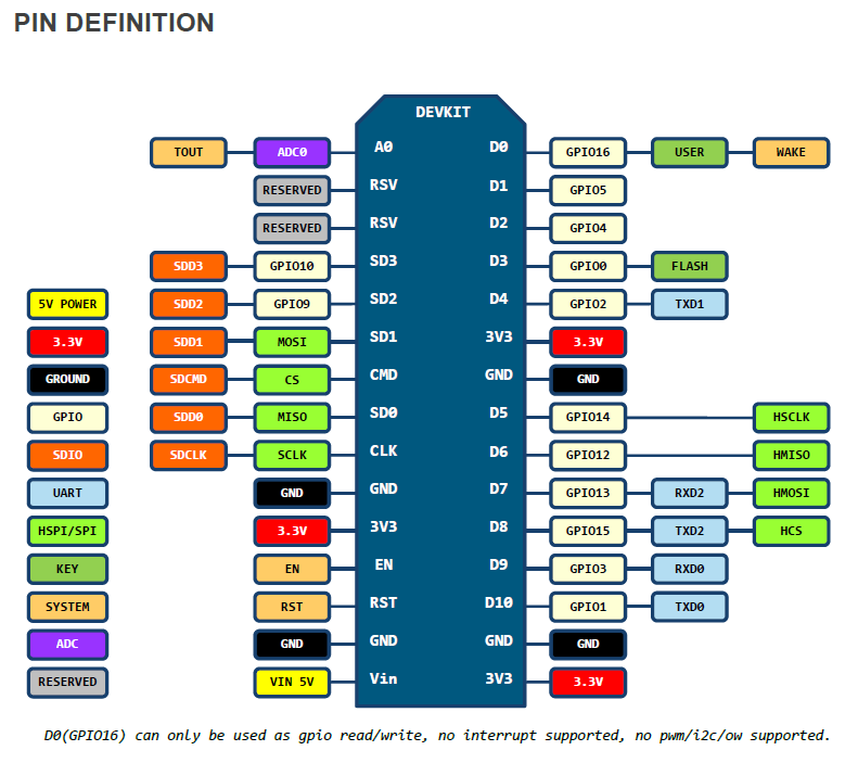
(Click here for a Pinout on the ESP-12, ESP-07 and ESP-01)
Now one important thing is that we have a limited amount of pins and we have to be careful which we use.
Those are the ones we can use for attaching the components:
| NodeMCU Pin | GPIO | Note |
|---|---|---|
| D0 | GPIO 16 | No i2c or pwm, sometimes used for board LED |
| D1 | GPIO 5 | |
| D2 | GPIO 4 | |
| D3 | GPIO 0 | Used for flash button |
| D4 | GPIO 2 | Needs pull-up resistor, used for module LED |
| D5 | GPIO 14 | |
| D6 | GPIO 12 | |
| D7 | GPIO 13 | |
| D8 | GPIO 15 | Needs pull-down resistor |
| D9 | GPIO 3 | RX (Serial) |
| D10 | GPIO 1 | TX (Serial) |
| SD2 | GPIO 9 | Used for Flash |
| SD3 | GPIO 10 | Used for Flash |
A few things are important to note here!
- D0 or GPIO 16 can't be used for a classical RGB LED (pwm) or for the display (i2c).
- D4 and D8 need resistors? Yes these pins are used for booting the device correctley. That's where the recommended 2 resistors come in place! Usually the development board already has such in place, but in case you use these pins and run into problems when uploading new code - that might be the reason! So keep in it in mind.
- D9 and D10 are used for serial and are, as such, essential to upload code and debug it. Don't use these pins unless you know what you're doing!
- D3 or GPIO 0 is used for the flash button. Usually that's not a problem, but again... if you run into problems when uploading, keep in mind that the pin is used to get the device into flash mode.
- SD2 and SD3 are used for the on-board SPI flash. You can use them safely as long as you don't select QIO in the upload/compile settings.
That leaves us with 7 safe to use pins and 4 more which we have to be a bit careful with.
Now you don't have to be a genius to figure out that if you want to use all 6 buttons (6 pins), a SPI display (4 pins) and a RGB LED (3 pins), 11 pins are not enough.
That's why it is recommended to use an i2c display (2 pins) or a neopixel/ws2812 (1 pin).
Also don't forget that you only need 3 buttons, every other button is optional.
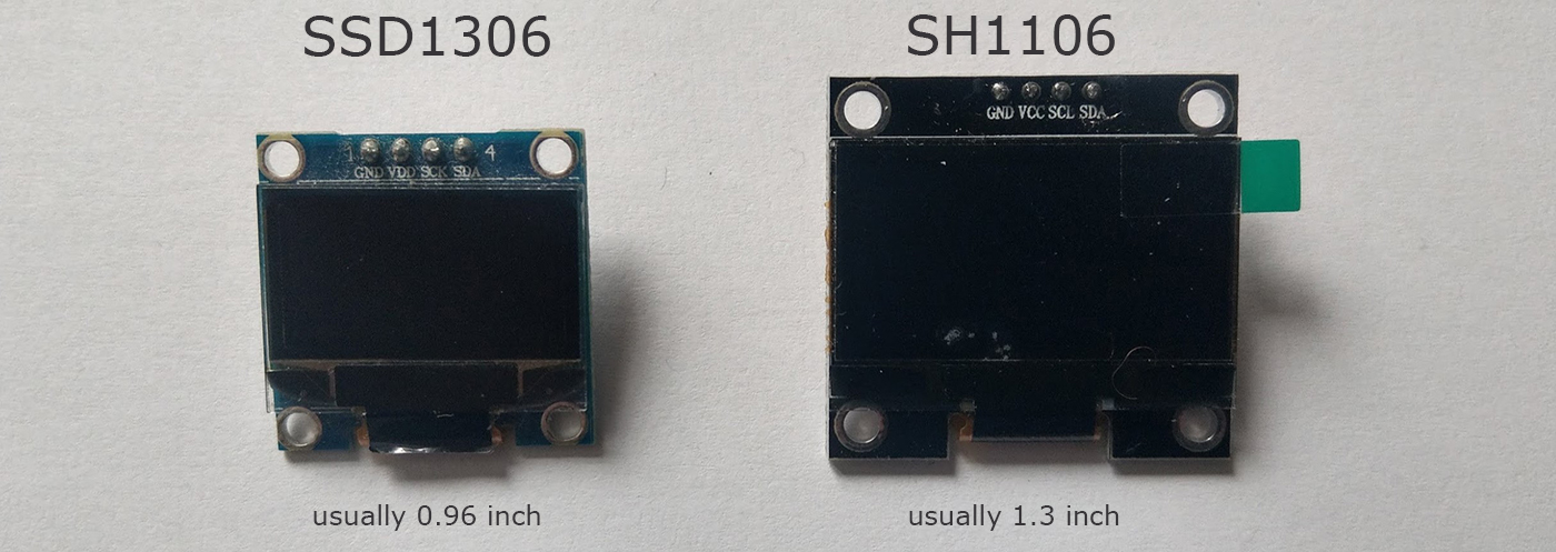
There are 2 types of OLED displays that can be used for this project, the SSD1306 and the SH1106:
And they sometimes come with either I2C or SPI:
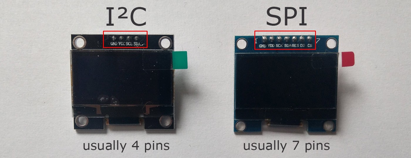
Now for the display it is very important that you know which connection it is using.
I2C can be connected to any GPIO pin (except 16).
The SPI however requires following connections:
| Display | GPIO |
|---|---|
| SCL/CLK/SCK | GPIO 14 (D5) |
| SDA/MOSI | GPIO 13 (D7) |
RST, DC and CS pins can connected to any pin.
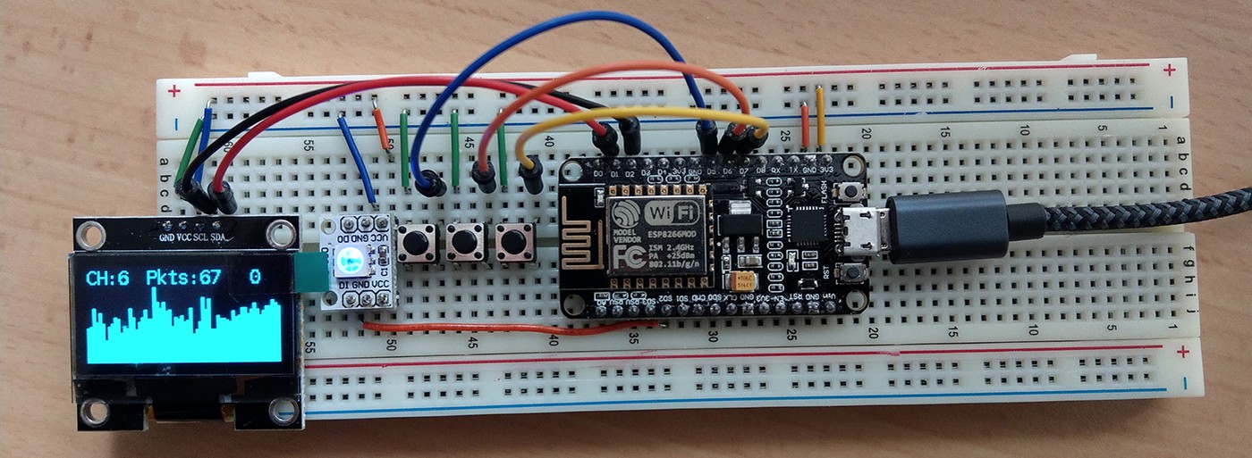
Best practice is to make a list of all components and their connections!.
The buttons are pretty simple.
You need to connect each of them between a gpio pin and GND.
Like in this Arduino tutorial: https://www.arduino.cc/en/Tutorial/InputPullupSerial
The LED(s) is completley optional. It's used to give the user a better indication of what the device is currently doing. For example Green = idle, Blue = scanning, RED = deauth attack detected (when scanning).
You can use single digital LEDs, a RGB LED or a neopixel LED (ws2812).
By default the LED on GPIO 16 (NodeMCU on-board LED) and the LED on GPIO 2 (ESP-12 and ESP-07 on-module LED) are used. So be sure to disable them if you want to use those pins for something else.
| Display | GPIO |
|---|---|
| GND | GND |
| VCC/VDD | VCC / 3.3V |
| SCL/CLK/SCK | GPIO 4 (D2) |
| SDA | GPIO 5 (D1) |
| Button | GPIO |
|---|---|
| UP | GPIO 14 (D5) |
| Down | GPIO 12 (D6) |
| A | GPIO 13 (D7) |
| NEOPIXEL LED | GPIO |
|---|---|
| GND | GND |
| VCC | VCC/3.3V |
| DIN | GPIO 9 (SD2) |
| Display | GPIO |
|---|---|
| GND | GND |
| VCC/VDD | VCC / 3.3V |
| SCL/CLK/SCK | GPIO 14 (D5) |
| SDA/MOSI | GPIO 13 (D7) |
| RST/RES/RESET | GPIO 5 (D1) |
| DC | GPIO 4 (D2) |
| CS | GPIO 15 (D8) or GND |
| Button | GPIO |
|---|---|
| UP | GPIO 0 (D3) |
| Down | GPIO 12 (D6) |
| A | GPIO 2 (D4) |
| NEOPIXEL LED | GPIO |
|---|---|
| GND | GND |
| VCC | VCC/3.3V |
| DIN | GPIO 9 (SD2) |
Now that your setup is done, you have to make some changes to the code.
-
See Installation on how to compile and flash this project using Arduino.
-
In Arduino under
tools>Deauther ConfigselectDisplay Example I2CorDisplay Example SPIdepending on your setup -
In Arduino and open the
A_config.hfile (second tab) -
Scroll down to
#if defined(DISPLAY_EXAMPLE_I2C)or#elif defined(DISPLAY_EXAMPLE_SPI). -
If you used other pins than mentioned in the example setup above, this is where you can change them.
For example, you might need to change#define SH1106_I2Cto#define SSD1306_I2Cdepending on the type of display you are using.
Or#define SH1106_SPIto#define SSD1306_SPIif you're using a SPI display. -
In Arduino under
tools>Erase FlashselectAll Flash Contents. This will make sure your changes are applied and override any old settings. -
Now make sure you selected the correct port and upload! If something isn't working correctly, check the connections and your adjustments from step 5.
Now when everything is correctly setup and uploaded, you have to open the serial monitor with arduino.
Make sure to set the baud rate to 115200 and select Newline.
If you see that the device is resetting every few seconds, check the code! Most of the time it's that you used one pin for both the display, button or LED.
Be sure not to have used the same pin for multiple things, not on the breadboard and not in the code!
Still no image on the diplay? Type in set display true;;save settings and press enter. Now press the reset button on the board to restart it. If the dislpay doesn't show anything, something is off. Check your connections and your code!
To see if all buttons are working correctly use the screen mode buttontest command. To get back use screen mode menu.
If you have problems with the display, try using other software that uses the display. That way you will know if it's a software or a hardware problem.
Here's the display library used for the deauther: https://github.com/squix78/esp8266-oled-ssd1306
You can find examples there, try to get those running.
To test the LED(s), you can use the led <r> <g> <b> command. For example led 255 0 0 should turn on only the red LED.