Datasheet
OpenLog is a simple serial logger based on the ATmega328 running at 16MHz. OpenLog is able to talk to very large capacity (tested up to 64GB) SD cards. The whole purpose of this logger was to create a logger that just powered up and worked. OpenLog ships with a standard serial bootloader so you can load new firmware with a simple serial connection.
###The Basics###
- OpenLog runs at 3.3-5V at 9600bps by default. The baud rate is configurable from 300bps to 1000000bps. We recommend you modify the config file to work at a different serial speed, but you can also reconfigure OpenLog via software commands. See the command example sketch for more information.
- The microSD card can be any size from 64MB to 16GB. Before using OpenLog be sure to format the card either FAT16 or FAT32. We recommend using Windows to format your card. If using Linux, be sure to create a DOS filesystem after formatting the card.
- During power up, you will see 12> or 12<. 1 indicates the serial connection is established. 2 indicates the SD card has been successfully initialized.
- < indicates OpenLog is ready and will log any serial data received (this is the default mode)
- > indicates OpenLog is ready to receive commands.
- Type ? at the > prompt to bring up a list of supported commands.
- If you are actively logging in NewLog or SeqLog mode, sending Ctrl+z (ASCII 26) three times will exit logging mode and enter command mode.
- For a full list of commands, see the Command Set page.

###Connections###
- GRN: Reset pin and connects to the GRN pin on the Arduino Pro Mini. Pulling this line low will reset the ATmega328. Because there is a capacitor on this line, holding this line low will not keep OpenLog in reset.
- RXI: Serial input into OpenLog.
- TXO: Serial output from OpenLog.
- VCC: 3.3V to 12V input. We recommend 3.3V to 5V.
- GND: Ground
- BLK: This pin is connected to GND. Connect this pin to BLK on the Arduino Pro Mini.
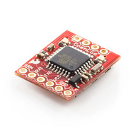
The four pins shown at the top of the board are connected to the SPI pins for programming. We use a special pogo-pin jig to program the serial bootloader onto each board. You are welcome to connect to them but realize the SPI pins are shared with the interface to the SD socket so you might not want to use them as GPIOs. From left to right, the pins are RST, SCK, MOSI, and MISO respectively. You can find more information regarding this in the Eagle files.
###Status LEDs###
- STAT1 LED is the LED shown above, right of the word OpenLog and is sitting on PD5 (Arduino D5) This LED toggles on/off every time a new character is received. This LED helps troubleshoot and indicate serial communication is working.
- STAT2 LED is the LED shown above, left of the word OpenLog and is sitting on PB5 (Arduino D13) This LED is attached to the SPI Serial Clock line. You will see this LED flash rarely. It only turns on when the SPI interface is active and this is rare as the OpenLog buffers 512 bytes at a time before recording to the SD card. Recording 512 bytes is very fast so the LED is on for very little.
###Features###
- Supports automatic log generation and recording. Turn on OpenLog, wait ~2 seconds and start throwing text at it!
- Supports any baudrate from 300 to 1,000,000 at 8-N-1.
- Supports 8.3 file names. "12345678.123" is the longest name.
- All file names are alpha-numeric. "MYLOG1.SZZ" is ok, "Hi !e_.txt" may not work.
- Recording constant 9600bps datastreams are supported. Throw it everything you've got! Higher datarates are supported with some considerations.
- The change directory command is a bit weird. Normally it's 'cd..' but to change to a lower dir, use 'cd ..' (space between cd and ..)
- If you get OpenLog stuck into an unknown baudrate, there is a safety mechanism built-in. Tie the RX pin to ground and power up OpenLog. You should see the LEDs blink back and forth for 2 seconds, then blink in unison. Now power down OpenLog and remove the RX/GND jumper. OpenLog is now reset to 9600bps with an escape character of ctrl+z sent three consecutive times. Note: This feature can be overridden if needed. See configuration file for more information.
- Pre-programmed STK500 (Arduino Uno compatible) serial bootloader running at 57600bps @ 16MHz with Optiboot improvements.
Bootloader Note: The preloaded Optiboot serial bootloader uses the upper 500 bytes of flash. If you are modifying the stock OpenLog firmware and the new code is larger than 32,256, you will get verification errors during serial bootloading. Warning: some early units (sold in December of 2009) of OpenLog did not have a bootblock protection lock bit set and will overwrite the bootloader. To check if you have one of these versions, drop to command mode and type ?. The OpenLog firmware version number is shown at the top of the menu. Everything after v1.0 (v1.1 and above) is good and does not have this problem.
###Power### Input voltage on VCC can be 3.3 to 12V. Input voltage on RXI pin must not exceed 6V. Output voltage on TXO pin will not be greater than 3.3V. This may cause problems with some systems - for example if your attached microcontroller requires 4V minimum for serial communication (this is rare).
OpenLog has reverse power protection. The Micrel voltage regulator can take some serious abuse (reverse power applied, over current shut down, over voltage protection). All parts are static sensitive, but the ATmega328 and Micrel regulator have built-in static protection.
Current consumption:
- 2mA Idle
- 6mA Actively writing to a file
6mA is rare. The vast majority of the time OpenLog is idle. Writing to the SD card (6mA) happens once a 512 byte buffer fills up. Recording that buffer completes in a fraction of a second so the average consumption is very near 5mA unless you are pounding the serial port at 115200bps with a constant data stream.
Note: OpenLog may lose characters if power is removed. During an append, OpenLog will buffer 512 characters at a time. That means that if the system loses power while reading in characters, you may loose up to, but no more than, 511 characters. This is important for low power systems where you may not know when the battery or power will die. OpenLog should record each buffer as it receives each 512 byte chunk. The only way to exit an append is with Ctrl+z (ASCII 26). In firmware v1.3 and above, OpenLog has an auto-store feature. If OpenLog is idle for more than 2 seconds, it will auto-save any characters in the buffer. This is very helpful for systems that store a few characters every few seconds. This feature also significantly saves on power.
###Dimensions###

###Troubleshooting###
The easiest way to get OpenLog working is with a serial connection to a computer. Power up OpenLog and you should see 12<. If you don't, make sure your TXO and RXI pins are connected correctly. TXO is an output pin from OpenLog and will need to be connected to a input pin on your serial conversion board.
I don’t know what baud rate I put it into! Help! Emergency reset - aka factory defaults. If you get OpenLog stuck into an unknown baud rate, there is a safety mechanism built-in. Tie the RX pin to ground and power up OpenLog. You should see the LEDs blink back and forth for 2 seconds, then blink in unison. Now power down OpenLog and remove the RX/GND jumper. OpenLog is now reset to 9600bps. After a power up you should see 12<. To get OpenLog into command mode, press ctrl+z three times.
OpenLog communicates with TTL, not RS232, because it is meant to be connected with a microcontroller or an embedded project. If you are connecting OpenLog to a computer, you will need a TTL-to-RS232 converter board such as the RS232 Shifter board, FTDI Basic, or the FT232 Breakout.
OpenLog has two onboard LEDs. STAT1 will blink with an error code if something is wrong. Currently there are two error codes:
- 3 Blinks: The SD card failed to initialize. You may need to format the card with FAT/FAT16 on a computer.
- 5 Blinks: OpenLog has changed to a new baud rate and needs to be power cycled.
The Card Detect feature of the microSD socket is connected to the ATmega328 but we are not currently checking for physical presence. This is because there are some SD sockets that have this feature available, and some that do not. When we began production of OpenLog we were not sure which socket would be available so we skipped this check in the firmware.
What is the limit on the number of files I can create in the root directory? Currently the log number limit is 65,534. You can load hundreds of files into the root directory, but OpenLog will perform more and more slowly as more files are introduced. We recommend logging to a freshly formatted FAT16 microSD card. 100 or 200 files/logs is fine. As you approach thousands of files OpenLog can take multiple seconds to create a new file and start to log.
What is the limit of sub-directories I can create? OpenLog currently supports two sub directories but can be increased by changing the code, recompiling, and loading the new firmware onto OpenLog. Change the definition of FOLDER_TRACK_DEPTH from 2 to the number of sub-directories you need to support.
Example Arduino Code: The easiest way to use OpenLog with an Arduino is to simply attach the RXI pin on the OpenLog to the TX pin on the Arduino. Anything that the Arduino outputs (sensor readings, GPS coordinates, etc) will be recorded.
Serial.begin(9600); //9600bps is default for OpenLog
Serial.println("123");
will cause the Arduino to output 123 at 9600bps and will be logged by OpenLog. There are multiple example sketches available in this repository. If you don't know how to use Github, download this entire repo to get the example Arduino sketches and then checkout this tutorial on how to use Github.
Example C Code: You will need to setup your microcontroller to output serial streams at 9600bps 8N1. Almost all microcontrollers now have a UART and are configurable for this setup.
How do I attach a FTDI Basic board to OpenLog for configuring and bootloading? You can not attach an FTDI Basic or FTDI Cable directly. This is because you have to swap TX and RX.

It's easiest to use a breadboard to make the connection from an FTDI to an OpenLog.
But once you've swapped TX/RX, you can easily use an FTDI Basic to talk to, configure, and quickly bootload new firmware onto OpenLog.
Why in the world did you do mess up TX and RX like that? Most of the data logging projects (such as logging the temperature of your compost pile over 3 months) take place away from a computer. Therefore, OpenLog will probably not be connected to a computer - instead, it will likely be connected to a microcontroller. We made OpenLog so that it can plug directly onto an Arduino Mini Pro
How do I upgrade the firmware on OpenLog? See the Flashing Firmware page for more information.
How do I compile OpenLog? See the Flashing Firmware page for more information.
OpenLog Wiki Pages: