ADNS-7550 laser sensor chip for quadrature output mouse
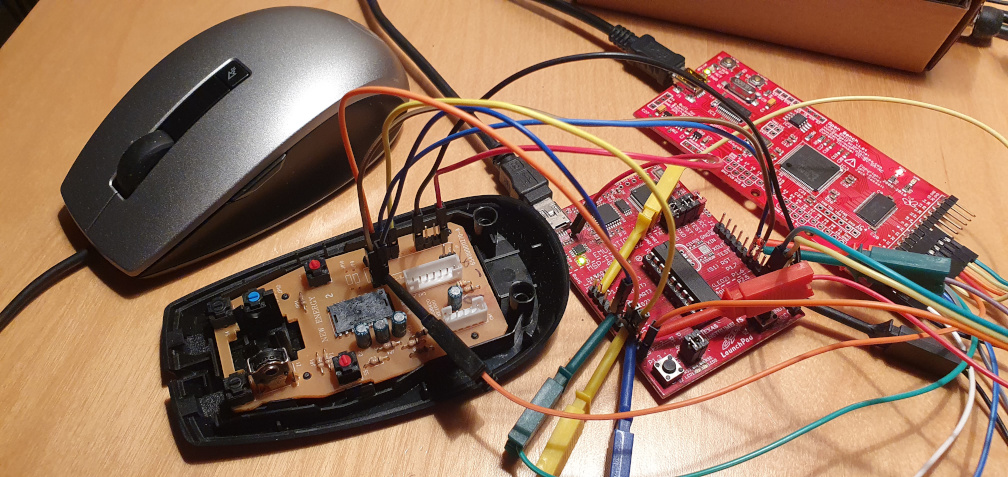
This project is based on a Dell mouse which is run by an unknown micro-controller, and SPI ADNS-7550 sensor chip. It made a very easy for me to modify it and drop in msp430g2553 micro-chip in the same spot, after a handful of easy modifications: trace-cuts, and wire jumpers. A full schematic is missing but the pin assignment should tell whole story:
                                 ______________
                            Vcc  | 1       20 | GND                DB9 8
               top button   P1_0 |            | P2_6   QRA
               MOTION/IRQ   P1_1 |            | P2_7   QRB
                      CS    P1_2 |            | TEST
        DB9 5         MMB   P1_3 | 5          | RESET
                mmb-in      P1_4 |            | P1_7   MOSI
                      CLK   P1_5 |            | P1_6   MISO
   XQ   DB9 4         QXA   P2_0 |            | P2_5   5th button
    X   DB9 2         QXB   P2_1 |            | P2_4   4th button
    Y   DB9 1         QYB   P2_2 |_10______11_| P2_3   QYA      DB9 3 YQ

mouse pinout DB9:
     QYB QXB QYA QXA
      Y   X  YQ  XQ  MMB     DB9   color   UTP         MCU
      U   D   L   R  PotY      1   red     w/grn         10
   _______________________     2   blk     w/brw          9
   \  1   2   3   4   5  /     3   gry     w/blu         11
    \                   /      4   org      org           8
     \__6___7___8___9_ /       5   brw      brw           5
       LMB  +  gnd RMB         6   grn      grn         LMB
                   PotX        7   wht      blu       +5vcc
                               8   blu     shield       GND
                               9   ylw     w/org        RMB
Among not included components in the above schematics is 3.3V regulator, necessary to run MSP430 at it maximum clock 16MHz. It is supplied from 5V at pin 7 of DB9 port. Wire colors listed are for own reference (happened to be the one in the game controller replacement cable (DB9) offered on one of the far-east on-line retail shop)
Before desoldering controller chip from the original mouse, dump the calibration values that are send during boot-up. Write down what values are written to register 0x1a LASER_CTRL0/1 (0x1f) and 0x1c LSRPWR_CFG0/1 (0x1d). See datasheet page 7 for details.
- at constant intervals (
VerticalBlankISR), host is polling with a low level at MMB line - controller reacts at the falling edge of MMB linkage (see marker 1 - blue line MMB)
- quadrature lines are negated with command for a brief moment (20us ... 40us) (see marker 2 - lines QXB and QYB)
- after restoring original state of quadrature lines, state of MMB is checked to verify reception
- if MMB line is still low - treat transaction as successfully (see marker 3)

Corresponding host driver software can be obtained from AmigaMouse repository.
Case can be easily opened, even without removing front latches. Pins 1 (Vcc), 20 (GND), 16 (RESET) and 17 (TST) can be reached with small programming terminals (clips).
