Works with USB power, not with battery? #20
Comments
|
Just received my new (WHITE PCB) version and can echo the same here - Works fine on USB, appears to charge when an LIR2450 is in place (blue LED) and USB plugged in. Can switch on with an LIR2450 and USB connected, and interestingly when I disconnect the USB while still on it still works. Switch off and back on with just the LIR2450 and no power.. Have not looked into testing where power getting to, and also just testing another LIR2450, but this is odd behaviour indeed! It's like the USB connection trips it on, and without that initial USB trigger, it doesn't power up? @codepope - if your board is working with both USB and LIR connected, disconnect the USB and does it still work on the battery? And then when you switch off and on, does it then fail to boot up? Would be worth people advising which boards they have, I.E. I now have a blue PCB version with programming headers, and now a super cool white PCB with a serial-USB programming chip on the USB (very cool additon!) |
|
That's exactly what I'm seeing. (White PCB too). USB+LIR boots, pull the USB, it carries on running, then switch off and back on and it fails to boot up. |
|
hmmmm, maybe the power regulator is not detecting the battery voltage to switch on? Trying another battery here, but sounds like a valid problem. |
|
Seems to be another symptom - when you do the switch on with USB and then pull the USB the default sketch reports multiple incorrect directions selected when the stick is touched. Plug the USB back in and it reports as normal. |
|
Yes(!), did not notice that, but now also seeing that the button message reports randomly when going from USB to BATT, and it tends to report multiple button presses, and incorrect ones. It's actually reporting multiple presses as I type this and I am not touching it. Sounds like the button is not being de-bounced correctly, or something to do with the ground - unless on USB which may be grounding things correctly?? Could also tie in with the battery issue, maybe there is an incorrect ground issue when running on battery, so it won't boot up from battery? |
|
Also - not sure if this is part of the schematic, but if you plug in the USB with switch ON (after it runs on BATT), it does not work. Switch if off and on again with the USB still plugged in, and it still does not work. I have to remove the USB, switch OFF, and then plug in the USB and switch ON. This is not how the blue version of the board works. Additionally to the previous post - running on BATT when you power up with USB and then remove it - the Badgy stops responding after several minutes. So maybe it's not running on battery at all, but some residual energy stored up in the capacitors, but that doesn't make much sense?! I am going to poke about with a multimeter and see what voltages we are seeing. Have tried this with three LIR2450 batteries too. |
|
@sqfmi - any thoughts on this odd behaviour of the new boards? Noticed the use a new charge IC too, the TP4054. |
|
Same exact issue here :( New white PCB. Tried two different fully charged batteries. @sqfmi any thoughts? |
|
Oh ho.... Huston, we have a problem..! 😣 |
|
Sounds like it could be a hardware issue with the new batch, let us investigate the issue and get back to you guys shortly. |
|
I just received 2 white PCB units and can also confirm that they do not boot, or even power the esp on battery power. |
|
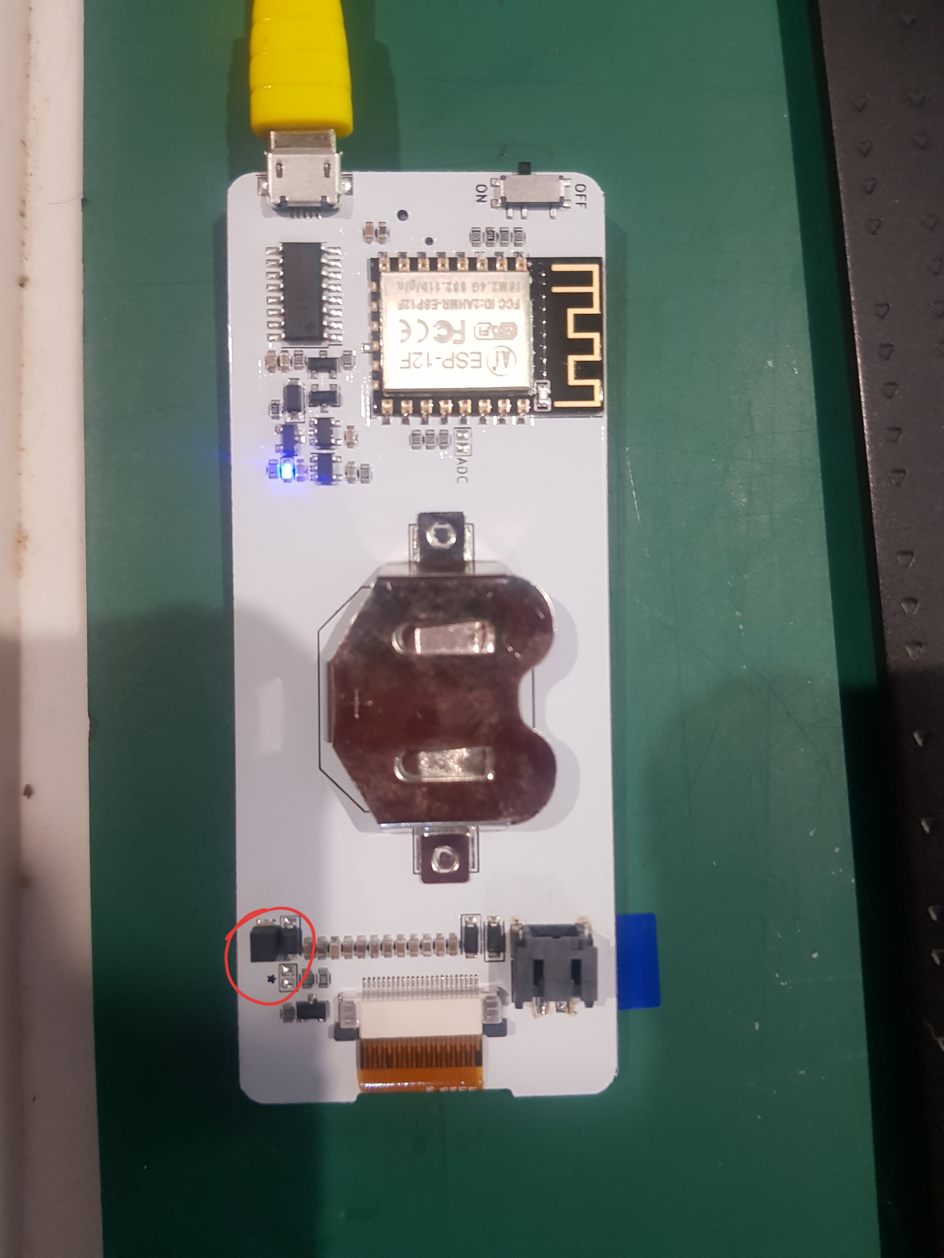
Brief update, it seems while on battery power only, you are able to turn it on by resetting it. This can be done by using a metal object to short the reset pin with the metal shield (e.g. paperclip, key, etc.):
Hacky solution for now, will continue to diagnose the root cause. |

|
Doesn’t seem to be working for me. |
|
I can confirm this hack works for me and boots the ESP8266 on battery power. A better connection to "tap" @codepope would be the lower pad of the Lipo JST connection (which is ground). Not the upper pad as that is the positive to BATT. The casing didn't seem to give a good reliable ground connection, but turn on the switch, put a wire (I used a dupoint breadboard wire) on the RESET pin imaged above, and then tap the lower JST pad - the ESP should flash it's blue light on boot. (don't tap the left side pads of the JST connection, these don't seem to be tied to ground, just mechanical fixings) |
|
@chunkysteveo Yes, the JST pad is easier to tap, but still no joy. To ensure I was getting a reset, I applied USB power and ground tapping the reset line did reset. |
|
hmmm, not good. Assume battery is fully charged too? Some flake-y issues going on to be sure! Hopefully there will be a fix soon, even if it's a bodge wire fix...!? |
|
Well, I thought it was, but testing says otherwise. Tried another battery which shows charged and it didn't play ether. |
|
As a temporary fix, I added a reset button between the ground pad on the JST connector, and the RST pin on the ESP8266. Also threw on a JST connector and LiPo battery since I didn't have a proper coin-cell size LiPo. Now I just power it on, and click the reset button to boot the ESP8266. It would be nice to know what the actual issue is, but this works for the time being.
|

|
can we have schematics for this version?pretty please? :) the switch behaves strange,i want to know what i'm doing |
|
I put in a LIR2045 and tried the bodge wire with no luck. It does work with the USB power though. I just probed and found that with a LiPo battery I get 4.0v at the JST connector and only 3.2 at the ESP8266 reset pin. When I ground it, it does nothing at all. Disconnected my color screen to see if that was causing something and still no response. |
|
@Korenchkin yes! Thank you for the reminder :) The new schematic is in the hardware folder now. Everyone else, sorry we're still trying to debug the issue :( |
|
thanks for the schematic!i tried to find the problem,but this makes my head hurt..everything seems okay for starting,i'd try pulling the usb chip and stick with prog header(i'm guessing some leakage to ground),but maybe somebody will make smarter solution..like cap on reset?tried that,but did not work for me..but at least i know what the switch switches... |
|
Removing the CH340C does seem to work! But the reason is unclear at this point... we'll try to do some further investigation with a scope. |
|
I would like to go on the record as saying that the CH340 is the devil's brood. I flipping hate those things |
|
@sqfmi If you're looking for better alternatives to the CH340, I'm a big fan of the SiLabs CP2104. Adafruit uses them for all their newer dev boards. High data transfer rates, better driver support than the CH340, and cheaper than an FTDI. |
|
Just a theory,could the ch340 be pulling down gpio0 and/or reset over the 2 transistors?maybe only on start befor it semi-charges its vcc cap?then there are only rx/tx pins,they should not do anything high or low,and that seems all the influence it can do powered off |
|
@sqfmi Hmm.. Reset didn't work for me - the LED on the ESP8266 blinks when reset - but nothing. In fact, I get absolutely nothing happenng now :( sketches won't upload and the currently loaded sketch (weather) won't refresh :,( Oh, and the circled component is scortching hot - |
|
Can you upload a sketch via the USB 2 serial? |
I am also suffering from this major issue which makes the Badgy basically 99% useless. |
@chunkysteveo I observed that too. It certainly has to do with the fact that the UP/DOWN buttons use the same pins as the Serial TX/RX and that bloody CH340 is playing on those sending "phantom button presses"... |
|
@sqfmi - the issue occurred after uploading the weather sketch and resetting the ESP8266 as described in the 'Hacky solution' from October 8th above :(
|
|
Any updates on the diagnostics, the CP "hack" PCB's, any other fixes, revisions of the PCB @sqfmi ? |
|
Sorry about the delay, we've had trouble finding a fab that could mass produce the CP2014 adapter boards for us. We're in discussion right now with a promising vendor at the moment. We'll keep everyone posted on any new updates and an ETA when it becomes available. |
|
That's good, was worried that the project had been abandoned. Do you have the board files available (the add-on board) for anyone that would like to make the CP2104 themselves? |
|
Added GERBER files for the board https://github.com/sqfmi/badgy/tree/master/hardware/CP2104_Adapter |
|
Brilliant, i'm sure it will help a lot of guys out. I may even try and solder one up...! |
|
Only just spotted your link to the original board project on Oshpark, I could have used that link, apologies!! Just out of interest, does anyone know the difference between the CP2104-F03-QFN and the CP2104-QFN? Assume the F03 is a new version, as the "non" F03 chips are cheaper? |
|
I've just ordered the PCB from OHS Park - What's the difference between CP2104-F03-GMR and CP2104-F03-GM - does it matter? Just wanting to get the IC on the way, too :) |
|
They are the same part, the difference is just in packaging (R stands for reel) |
|
Are the boards currently sold on Tindie still suffering from this issue, or have they been updated? Thanks! |
|
@jcaron23 all new boards will come with the CP2104 instead of the CH340C, which does not have the battery issue. FYI we found a fab to create the adapter boards for us, we are now waiting for the CP2104s to arrive so we can begin testing it out. If they work ok, we will be offering them to those who were affected by the issue.
|
|
Awesome news!! |
|
Is there any alternate fix for those of us with the old board, as shorting the reset pin didn't work for me? |
|
What's the difference between the CP2104-F03-QFN and the CP2104-QFN? @MarquisdeGeek - you can snip the VCC pin of the CH chip to disable it. You will lose the ability to program it via USB though. |
|
@chunkysteveo - Thanks, but that's a bit drastic for me! |
|
@sqfmi Hi, I have one of the blue PCB models which was bought in July last year and I suffer from exactly the same behaviour as described on this post. Any idea what's happening? |
|
@emanuelstanciu - I would recommend starting a fresh issue with this problem. This issue is related to the USB to serial chip not allowing the ESP8266 to boot when on battery. The blue PCB version does not have any USB to serial chip, so whatever issue you are seeing, it isn't to do with this issue. I don't want your issue to be lost in this bigger post! If the blue light flashes, that would indicate that it has booted and is powered. Something else is not working here? Steve |
|
Any resolution here? I just got my badgy and was under the impression that the white REV B board did not suffer from this problem. I just got some fresh batteries and Badgy doesnt work at all on battery power. Can someone please advise. |
|
Hi @pingywon, are you using LIR2450 batteries? |
|
Not exactly. I have CR2450s |
|
You must use the LIR2450. The CR2450 is not rechargeable, and is also not the right voltage (3.0V), Check out the README for more details. |
|
OK Great. So My original assumption that the issue has been resolved in my Badgy is correct? |
|
Yeah, REV B does not suffer the power issue on battery when using a. LIR2450 rechargeable battery. |
|
What ever happened to the offer from March 1 about the CP2104 adaptor boards. Do we have to do |
|
Hey @Carltk, send us a message with your Tindie order number and we'll ship the adapter boards to your mailing address. Thanks! |
|
I also have 2 badgys with this issue. Any chance to get the adapter boards? Thanks! |
|
Hey @Springwald, send us a message with your Tindie order number and we'll ship the adapter boards to your mailing address. Thanks! |
|
What is the preferred channel to send the message, since I also need an adapter board? Thanks. |
|
Hey @MarquisdeGeek , reach out to us via Tindie with your order number, and we'll ship the adapter boards to your mailing address. Thanks! |
Set up badgy on USB power, things behave as expected. Board LED glows flickers blue. Board boots up.
Popped a LIR2450 in with no USB connection and... nothing. Won't wake up, won't reset for new sketches, no LEDs glowing.
Pop in USB with LIR2450 in place, board LED glows bright blue (charging?) and board functions.
Any suggestions as to trouble shooting this?
The text was updated successfully, but these errors were encountered: