Tutorial_11 : Seven Segment Multiplexing Library
This library is used to implement Seven-Segment multiplexing. This library currently supports display of numbers with or without dot, numbers/digits which are reversed upside down and custom symbols. The pre-requisites for this library are SevenSegment Library and Timer Delay Driver.
As we learned in SevenSegment Library, we need 8 digital outputs to control a single seven segment. There are many applications where we will need more than one seven segments. For example a digital clock, in which we will need at least four seven segments to display hour and minute digits. Which means we will require 8 x 4 = 32 digital outputs. While our Arduino Uno has only 20 pins. So it wont be possible to implement digital clock using Arduino Uno. So how to solve this problem? Seven Segment multiplexing is our answer to this problem.
By multiplexing seven-segment displays the number of pins required to drive the displays can be reduced. In this scheme we connect seven segments as shown below :

As shown above a pins of all seven segments are connected together. Similary b, c, d, e, f , g and h pins are connected together. While the common pins of each seven segments are kept independent. Eight pins i.e. a, b, c, d, e, f , g and h pins are connected to eight digital outputs while rest four common pins are connected to other four independent digital pins. So instead of 32 pins we required only 8 + 4 = 12 digital pins. Effectively we saved 20 pins.
The basic principal of operation is that we glow one seven segment at a time. So if we have to display 1234 on the seven segments,
- we first display 1xxx, where x indicates segment is off
- Then we display x2xx
- then xx3x
- finally we display xxx4
- then again we display 1xxx
- And process continues.
But this on/off switching of each segment is so fast that our eyes gets the illusion that all four seven segments are on simultaneously. However to implement the coding of seven segment multiplexing is bit complex. Further multi-tasking becomes even difficult when we write code for multiplexing. SevenSegmentMulti library effectively solves this problem. Typical connections with Arduino Uno is as follows :

SevenSegmentMulti Library uses SevenSegment Library and TimerDelay Driver. Kindly refer these before proceeding further in this tutorial.
To include seven segment multiplexing header file in your code, you need to add following lines in your code :
#include "lib/SevenSegmentMulti.h"
#include "TimerDelay.h"
Since SevenSegmentMulti needs TimerDelay lib, hence its header must also be included. However, SevenSegment lib is included by default. You can also find sources for SevenSegmentMulti library here SevenSegmentMulti Lib
This Lib supports following initialization and functions :
First step is to initialize three variables
- Seven segment structure
- Seven segment multi structure and
- Array containing common pins.
These variables holds the essential data required by SevenSegmentMulti lib functions. Initialization is done as follows :
SevenSegment_t seg1 = {pin2,pin3,pin4,pin5,pin6,pin7,pin8,pin9};
SevenSegmentMulti_t multi_seg1;
mos_uint8_t seg_pins1[4] = {pinA0, pinA1, pinA2, pinA3};
In above declaration, first we have created a struct of type SevenSegment_t. We have assigned digital pins to struct which should be connected to Seven segment display in segment order A, B, C, D, E, F, G and H. Then we created a struct of type SevenSegmentMulti_t. This struct will hold all data needed by SevenSegmentMulti functions. And lastly we created an array seg_pins, which holds the digital pins connected to common pins of Seven Segments. All these variables should be defined above setup function.
Declaration :
void SevenSegmentMulti_begin (SevenSegmentMulti_t * seven_segment_multi_obj, SevenSegment_t * seven_segment_obj, mos_uint8_t * segment_common_pins, mos_uint8_t segment_count);
This function has four inputs, first is SevenSegmentMulti_t struct pointer, second is SevenSegment_t struct pointer, third is array which contains pins to connect to the common pins of seven segments and last is total segment count. Function is usually declared in setup function as
void setup(void)
{
SevenSegment_begin(&seg1, ANODE);
SevenSegmentMulti_begin(&multi_seg1,&seg1,seg_pins1,4);
TimerDelay.begin(TIMER_DELAY0,1,&timer_callback);
}
As shown above, it is important to note that before calling SevenSegmentMulti_begin function, SevenSegment_begin function must be called to initialize seven_segment_obj. Also we will need TimerDelay driver to run multiplexing code, so we need to include TimerDelay.begin function in setup as well.
SevenSegment_begin function simply initializes seg1 struct variable. Then this variable is passed as input to SevenSegmentMulti_begin function. SevenSegmentMulti_callback function is discussed in the next section.
Declaration :
void SevenSegmentMulti_callback(SevenSegmentMulti_t * seven_segment_multi_obj);
This function switches the display of digit after every call. For example, number to be displayed on seven segment array us 1234. The displayed numbers after every call of SevenSegmentMulti_callback functions are as follows :
- First call : 1xxx, where x indicates segment is off
- Second call : x2xx
- Third call : xx3x
- Fourth call : xxx4
- Fifth call : 1xxx
- And process continues.
This function must be periodically called. To do so we should use TimerDelay driver. As discussed in the introduction section, in seven segment multiplexing we switch on/off each seven segment one by one. This is implemented by periodically running SevenSegmentMulti_callback function using TimerDelay driver. In the below example, we are using TimerDelay.begin function to periodically run timer_callback function after every 1 milli-second. Which means we are switching seven segments on/off after every 1 milli second. TimerDelay driver is using TIMER_DELAY0 i.e. TIMER0 of atmega328P IC used in Arduino Uno. For more details about TimerDelay driver, please refer TimerDelay Driver. So code including timer_callback should look like this :
void timer_callback(void)
{
SevenSegmentMulti_callback(&multi_seg1);
}
void setup(void)
{
SevenSegment_begin(&seg1, ANODE);
SevenSegmentMulti_begin(&multi_seg1,&seg1,4,seg_pins1);
TimerDelay.begin(TIMER_DELAY0,1,&timer_callback);
}
Please note to periodically call SevenSegmentMulti_callback function, we should not use an independently running task for following reasons :
-
In Morey_os multi tasking is implemented using co-operative threads. Further, Morey_os is not a real time operating system. Hence Macros like DELAY_SEC or DELAY_SEC_PRECISE, do not guarantee to give exact specified delay at every run. While TimerDelay driver uses TIMER functionality of selected controller, hence specified delay is guaranteed.
-
Usually SevenSegmentMulti_callback function must be called after a very short duration like 1 milli-second or so. In a morey_os task, it is advised not to give the delay less than 0.05 seconds i.e. 50 milli-seconds using DELAY_SEC macros.
Declaration :
void SevenSegmentMulti_print (SevenSegmentMulti_t * seven_segment_multi_obj, mos_uint16_t number);
This function is used to print a number on a Seven segment array. It has two inputs, first is SevenSegmentMulti struct pointer and other is the number to be displayed. An example function call is :
SevenSegmentMulti_print(&multi_seg1,2345);
Declaration :
void SevenSegmentMulti_printDot(SevenSegmentMulti_t * seven_segment_multi_obj, mos_uint16_t number, mos_uint8_t * dot_position);
This function is same as SevenSegmentMulti_print with only difference that we can display one or more digits with dot. It has three inputs, first is SevenSegmentMulti struct pointer, second one is the number to be displayed and the last one is positions of digits with dots. An example function call is :
SevenSegmentMulti_printDot(&multi_seg1,2345,{0,0,1,0});
234.5 number will be displayed, which means third digit i.e. 4 will be displayed along with a dot.
Declaration :
void SevenSegmentMulti_printReverse (SevenSegmentMulti_t * seven_segment_multi_obj, mos_uint16_t number, mos_uint8_t * reverse_position);
This function is same as SevenSegmentMulti_print with only difference that we can display one or more digits in reversed manner. It has three inputs, first is SevenSegmentMulti struct pointer, second one is the number to be displayed and the last one is positions of digits to be displayed in reversed manner. An example function call is :
SevenSegmentMulti_printReverse(&multi_seg1,2345,{0,0,1,1});
Which means third and fourth digit, i.e. 4 and 5 will be displayed reversed.
Declaration :
void SevenSegmentMulti_printDotReverse(SevenSegmentMulti_t * seven_segment_multi_obj, mos_uint16_t number, mos_uint8_t * dot_position, mos_uint8_t * reverse_position);
This function is combination of SevenSegmentMulti_printReverse and SevenSegmentMulti_printDot. It has four inputs, first is SevenSegmentMulti struct pointer, second one is the number to be displayed and the third one is the positions of digits with dot and last one is the positions of digits to be displayed reverse. An example function call is :
SevenSegmentMulti_printDotReverse(&multi_seg1,2345,{0,1,1,0}, {0,0,1,1});
Which means Second and third digit will be displayed with dot and third and fourth digits will be displayed in reverse fashion.
Declaration :
void SevenSegmentMulti_customPrint (struct seven_segment_struct * seven_segment_obj, mos_uint8_t * * custom_data);
This function is used to display custom data on Seven Segment array. It has two inputs, first is SevenSegmentMulti struct pointer, second one is the two dimensional array. This two dimensional array should be of size 8 x segment count. An example function call is :
void SevenSegmentMulti_customPrint (&multi_seg1,{{0,1,1,0,0,0,0,0},{0,0,0,0,0,0,1,0},{1,1,1,1,1,1,0,0},{0,0,0,0,0,0,1,0}});
which will display 1-0- on the display.
Let us now check an example code named seven-segment-multiplexing that can be found in example folder (examples/board-examples/arduino-uno/seven-segment-multilpexing). The code is as follows :
#include "morey_os.h"
#include "TimerDelay.h"
#include "lib/SevenSegmentMulti.h"
SevenSegment_t seg1 = {pin2,pin3,pin4,pin5,pin6,pin7,pin8,pin9};
SevenSegmentMulti_t multi_seg1;
mos_uint8_t seg_pins1[4] = {pinA0, pinA1, pinA2, pinA3};
void timer_callback(void)
{
SevenSegmentMulti_callback(&multi_seg1);
}
void setup(void)
{
SevenSegment_begin(&seg1, ANODE);
SevenSegmentMulti_begin(&multi_seg1,&seg1,4,seg_pins1);
TimerDelay.begin(TIMER_DELAY0,1,&timer_callback);
}
TASK_CREATE(multi1,"Multi Seg-1");
TASK_AUTOSTART(&multi1);
TASK_RUN(multi1)
{
static int i=0;
BEGIN();
while(1)
{
for(i=0; i<10000; i++)
{
SevenSegmentMulti_print(&multi_seg1, i);
DELAY_SEC_PRECISE(0.01);
}
}
END();
}
- morey_os.h header file is compulsory to include in all codes. Since we will need TimerDelay lib functionality, we have added TimerDelay.h header too. Further we have included lib/SevenSegmentMulti.h header to use Seven Segment Multi functions.
#include "morey_os.h"
#include "TimerDelay.h"
#include "lib/SevenSegmentMulti.h"
We need to creat three variables. Struct seg1 of type SevenSegment_t
SevenSegment_t seg1 = {pin2,pin3,pin4,pin5,pin6,pin7,pin8,pin9};
SevenSegmentMulti_t multi_seg1;
mos_uint8_t seg_pins1[4] = {pinA0, pinA1, pinA2, pinA3};
- lcd is initialized with 16 cols and 2 rows in setup function.
void setup(void)
{
lcd_begin(&lcd,16,2);
Digital.pinmode(pina0,OUTPUT);
}
- We have created two tasks named lcd_test and led. Please note TASK_CREATE Macro has two inputs. First input is name of the task to be created, other input is string name of the task which is used during code debugging process. We will discuss more about code debugging in subsequent tutorials.
TASK_CREATE(lcd_test,"lcd_test");
TASK_CREATE(led,"led");
- Next we auto-start both the tasks at startup or powerup of the board. We can optionally start these tasks manually inside some other tasks. Starting or ending tasks inside a task will be discussed in subsequent tutorials. For now we will auto-start all tasks at controller/board boot time.
TASK_AUTOSTART(&lcd_test,&led);
- Next we declare TASK_RUN for both the tasks. lcd_test task implements all five functions namely LiquidCrystal_begin, LiquidCrystal_clear, LiquidCrystal_write, LiquidCrystal_print and LiquidCrystal_setcursor for lcd.
In TASK_RUN(lcd_test) a static integer variable 'i' is declared. Please note all variables in Morey_os must be declared as static. Reason for this is declared in subsequent tutorials.
After BEGIN(); Macro code implements a while(1) loop. Inside this loop, we have four different for loops. Each for loop implements moving message display. First for loop implements moving message starting from position (0,0) to position (15,0). You will notice that overflown text is going to next line. In each loop run, first LiquidCrsytal_clear function clears the LCD, then cursor position is selected using LiquidCrystal_setCursor, text is printed using LiquidCrystal_print function and finally we give delay of 1 second using DELAY_SEC_PRECISE(1) macro.
Similarly in second for loop moving message is displayed in second row, in third for loop moving message of single character 'A' is displayed in first row and finally in last for loop moving message of single character 'A' is displayed in second row.
To give delay in morey_os we can use DELAY_SEC() or DELAY_SEC_PRECISE() macros. Detailed discussion of these two macros is to be done in subsequent tutorials. Also it is very important to note that both tasks uses while(1) which is an infinite loop. Morey_os is based on cooperative threads, thats why this infinite loop must have at least one DELAY_SEC() or DELAY_SEC_PRECISE() macro. And we have used DELAY_SEC_PRECISE(1) inside for loops, hence this condition is satisfied.
TASK_RUN(lcd_test)
{
static int i = 0;
BEGIN();
while(1)
{
for(i=0;i<16;i++)
{
lcd_clear(&lcd);
lcd_setCursor(&lcd,i,0);
lcd_print(&lcd,"Morey_os");
DELAY_SEC_PRECISE(1);
}
for(i=0;i<16;i++)
{
lcd_clear(&lcd);
lcd_setCursor(&lcd,i,1);
lcd_print(&lcd,"Morey_os");
DELAY_SEC_PRECISE(1);
}
for(i=0;i<16;i++)
{
lcd_clear(&lcd);
lcd_setCursor(&lcd,i,0);
lcd_write(&lcd,'A');
DELAY_SEC_PRECISE(1);
}
for(i=0;i<16;i++)
{
lcd_clear(&lcd);
lcd_setCursor(&lcd,i,1);
lcd_write(&lcd,'A');
DELAY_SEC_PRECISE(1);
}
}
// process ends here
END();
}
- led Task simply switches pinA0 on and off after every 0.1 second.
TASK_RUN(led)
{
BEGIN();
while(1)
{
Digital.write(pinA0,HIGH);
DELAY_SEC(0.1);
Digital.write(pinA0,LOW);
DELAY_SEC(0.1);
}
END();
}
- Content of Makefile is as follows :
PROJECT = lcd-demo
MOREY_OS_PATH = ../../../..
BOARD = ARDUINO_UNO
include $(MOREY_OS_PATH)/Makefile.include
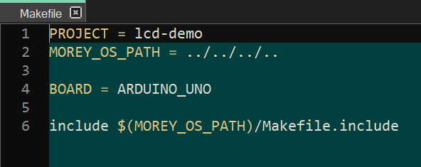
PROJECT Macro will hold name of the project file name. MOREY_OS_PATH holds the location of Morey_os root directory. BOARD Macro should hold ARDUINO_UNO since we are programming for Arduino_uno board. And last line should remain the same as mentioned above.
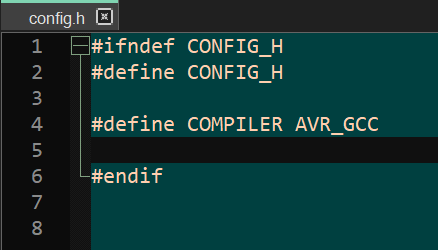
- This code is simple and requires no special configurations. Hence config.h file content will remain same as below :
#ifndef CONFIG_H
#define CONFIG_H
#define COMPILER AVR_GCC
#endif