The OpenBot open-source project started by Vladlen Koltun, former Chief Scientist of Intelligent Systems at Intel, provides the blueprint and software to create an inexpensive 3D-printed robot that leverages the smartphone as the brains. Inspired by this, I created my own software, hardware and chassis for a robot. My progress on this is shown below.
| Architecture | Chassis |
|---|---|
 |
 |
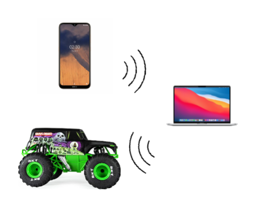
The overall design is to situate a cheap phone on the robot to wirelessly send visual information to a computer that will then process that information and send the appropriate command wirelessly to the bot, thus creating a closed loop system with visual feedback, as shown above. The design depends on the computer, phone and robot being on the same Wifi network because Wifi is used for wireless communication. A downside of this is some latency as well as being constrained to the physical area of the Wifi network. However, the benefits include allowing for scalable compute power, the ability to take advantage of desktop/server ML frameworks like PyTorch and Tensorflow with their large open-source communities and having a flexible coding environment that will allow for easy and powerful experimenting. Before this, the initial prototype had computation localized to the robot by having an iPhone situated on the robot that took in a visual feed, performed some computation and sent commands over Bluetooth to the robot, akin to the architecture of OpenBot. However, the mobile platform employing computer vision for perception proved problematic in quickly iterating. In addition, slow compile times and difficulties that arise from mobile programming made this first version a sub optimal platform for experimenting.
The important components of the robot platform are the phone/camera, the chassis, the electronic hardware in the chassis and finally the software stack processing visual input and sending commands to the robot.
For visual input, the only thing needed is a Wifi enabled camera. The Wifi enabled camera used is an inexpensive Android smartphone. This could not be used to run the robot, but it would be enough to stream a camera feed to the internet. I used an app called IPWebcam that set the phone up as a server on the local area network from which the camera feed could be accessed.
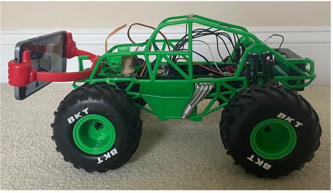
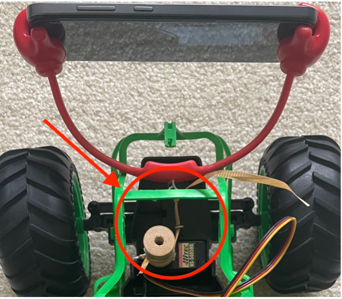
The chassis for the robotic platform is a retrofitted RC car. This obviates the need for a 3D printer. In addition, the RC car uses rack-and-pinion steering as used in automobiles instead of differential steering used in vehicles like OpenBot and tanks. Experimenting on a platform with rack-and-pinion steering is more difficult, but also far more enticing because it mimics how real cars operate. This allows experimenting with self-driving on a far smaller scale. Also, the chassis has a camera holder that can change the camera viewing angle of the phone by using a servo to reduce or increase the length of a supporting string that maps to a specific camera tilt as shown below.
| Circuit Diagram | Physical Mapping |
|---|---|
 |
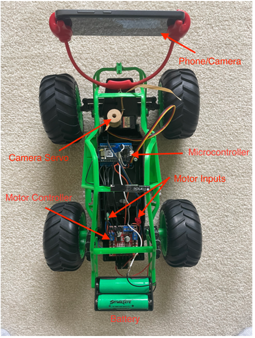 |
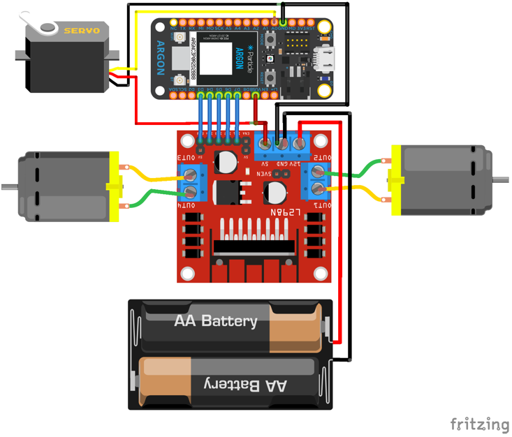
The hardware for the robot includes a few key components that allow for the robot to be wirelessly controlled. These components are a servo to control camera tilt, two motors to control the robot movement, a motor controller to allow for modulating power sent to the motors, a Wifi board to connect the robot to the central computer and a battery pack to power the whole system. The wiring between these components and details about them are below.
Motor Controller (L298N) The motor controller has the battery hooked to it as well as the two motors and the microcontroller. The battery is used by the motor controller to run the motors and to step down the voltage to 5V to power the microcontroller.
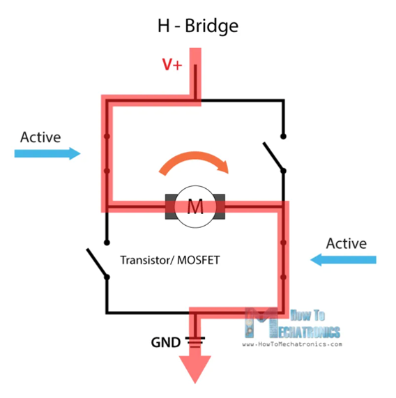
The motor controller specifically allows for the motors to turn in either direction and at a variable speeds. The motor direction is controlled by an H-bridge design which allows for changing the direction of current flow through the motor. The overall design of the H-bridge is that it has 4 transistors in an H configuration where one pair of diagonally placed transistors are active (i.e. closed circuit) and the another pair are non-active, forcing current to flow through motor in one direction. When this is reversed, current flows the other way, reversing the motor direction.
The motor controller controls the speed of the motors through standard PWM (pulse width modulation) being sent from the microcontroller. The controller is used for the motors steering the robot and propelling the robot forward.
Motors/Servo (RC Car) The motors were part of the RC Car that I retrofitted. They were initially connected to radio controller sold with the car. I removed the connections and connected them to the motor controller to verify they could run with PWM input like standard DC motors.
Microcontroller (Argon Wifi Board) The microcontroller is an Argon Wifi board that is used to control the robot wirelessly from a computer. It makes a socket connection with the computer and receives commands that it then uses to control the robot motors via the motor controller.
Batteries (3.7V Rechargeable Batteries)
The batteries used by the robot are 3.7 V lithium-ion rechargeable batteries. I wired them in series to get a total voltage of 7.4 V. I chose around 7.4 volts for a few reasons. First, it is above the 4.5 minimum voltage required for the motor controller. Secondly, it is enough above the 5 volts required to power the microcontroller and the motors that it can steadily provide 5 V.
The software run on the computer is a Python program that processes the camera feed from the robot and runs perception tasks. Based on results of this processing and some path planning techniques, it sends a command to the robot to help it reach a desired goal or destination.
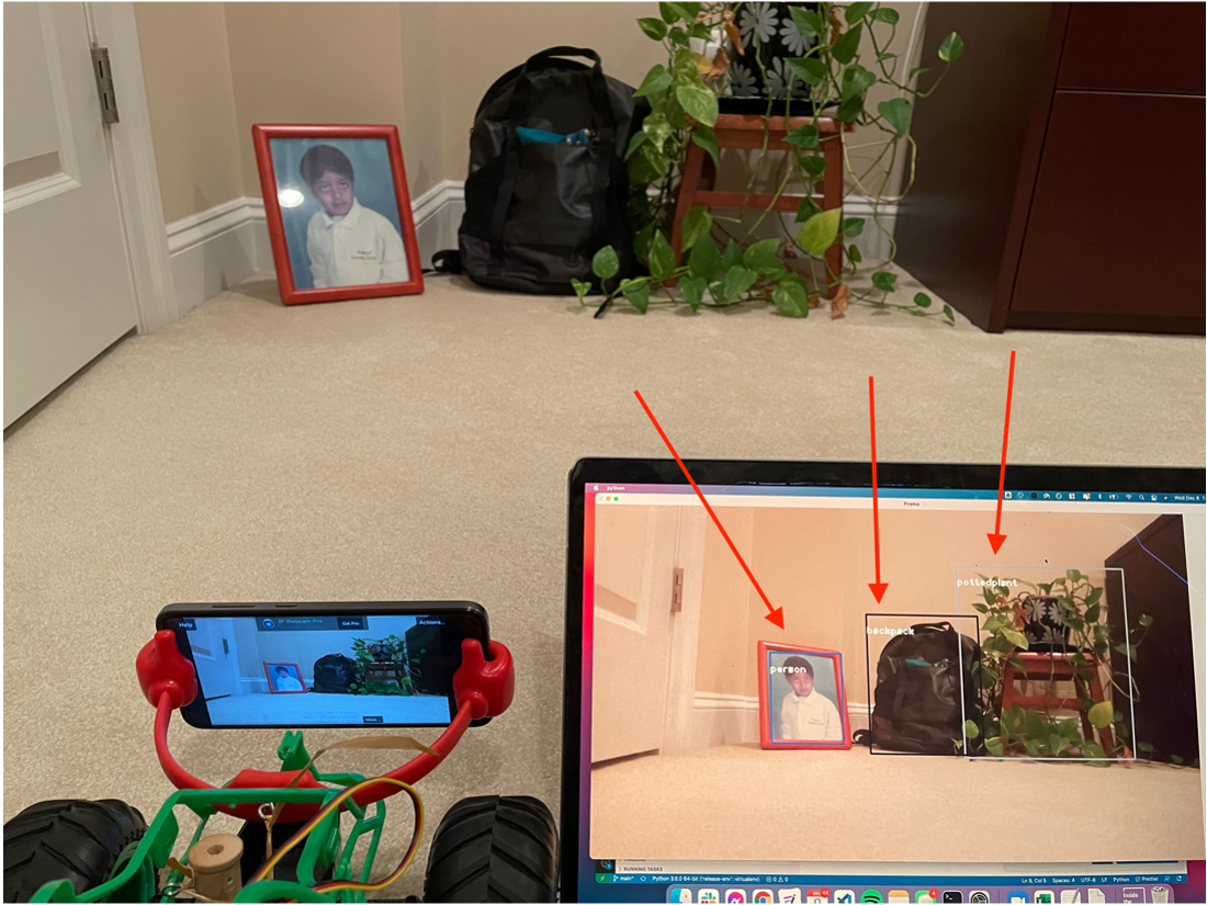
The perception tasks I ran were basic object recognition and depth perception. For object recognition I chose the YoloV3 algorithm that is well known to be a fast and reliable algorithm for drawing bounding boxes around certain objects. The results I got are shown below. They were reliable, but the fact that my laptop did not have an Nvidia GPU that PyTorch could take advantage of, the frame rate was low at 0.55 frames processed per second. I tried more compact versions including rewriting the neural net architecture (here) myself, but it did not work.
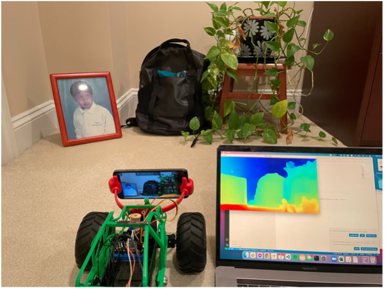
The depth perception neural net proved to face a similar issue. I was able to use an open source implementation of MiDaS that predicts the depth of every point of a single image with no additional information. It was able to run it a more respectable 2 frames per second, but it was still far too slow for real time navigation.
The last option left was a very simple perception algorithm that could only detect ArUco markers (used in augmented reality), but could do so very quickly with limited compute power. This resulted in a 5.1 fps processing rate. Putting an ArUco marker in the view of the robot, I was able to have the robot simply navigate towards it by centering it in the frame as the robot inched towards it. This very primitive path planning algorithm worked, but with many downsides. The first was the robot snaked in an S as it kept overshooting the target as it moved closer. My first step to improving this is instead planning a path composed of splines that align with the defined movement of the robot. While this is still far from perfect, it should allow for a far smoother trajectory.