For GSoC'22 a paper titled "On adaptive sliding mode control without a priori bounded uncertainty" has been implemented on a giraff robot using Robocomp framework visualised on Coppelia Sim to adaptively track a trajectory.
- Setting up Robocomp framework
- Usage
- Formulation
- Blog
The first step was to set up the robocomp enviroment with DSR-Cortex components, pyrep and Robocomp-giraff components. The path_planner_astar component is used to generate the trajectory to track. The mission controller component of robocomp-giraff component was used to give waypoints to the planner to generate a trajectory. Different environments of Coppelia sim were used to test the performace at sharp turns around different obstacles. This setup is used to test the performance of the controller.
- Install the robocomp framework
- Install Coppelia Robotics
- Install Pyrep
- Install cortex
- Install Robocomp Components
- Install Robocomp Giraff Components. Detailed Instructions here
To set up cpp binaries:
cd <path-to-the-component>
cmake .
make
Terminal 1: Start rcnode
rcnode
Terminal 2: Launch Coppellia Sim using Pyrep. Different maps can be choosen here by using different shell scripts.
cd ~/robocomp/components/robocomp-giraff/pyrep/giraff
./run_beta.sh
Terminal 3: Launch ID Server
cd ~/robocomp/components/dsr-graph/components/idserver
bin/idserver etc/config_giraff_beta
Terminal 4: Launch Giraff DSR
cd ~/robocomp/components/dsr-graph/components/giraff_dsr
bin/giraff_dsr etc/config_coppelia
Terminal 5: Launch Mission Controller
cd ~/robocomp/components/robocomp-giraff/agentes/mission_controller_giraff_mod
bin/mission_controller_giraff etc/config
Terminal 6: Launch path planner A-star
cd ~/robocomp/components/dsr-graph/components/path_planner_astar
bin/path_planner_astar etc/config_giraff_beta
Terminal 7: Launch path follower ASMC
cd ~/robocomp/components/dsr-graph/components/path_follower_ASMC/
bin/path_follower_ASMC etc/config_giraff_ASMC
All these could be run using a yakuake script named start_giraff.sh
To install yakuake
sudo apt-get update
sudo apt-get -y install yakuake
To give a waypoint to giraff to move:
- In the mission controller UI, choose the
Giraff Plan Controller - Choose
go to xoption from the dropdown menu - Choose the waypoint by right clicking on the map and click start
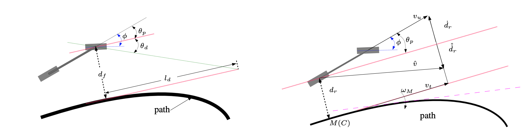
The current path_follower DSR Component in the Robocomp framework is a Stanley Controller.
Stanley Controller Law is given by
This controller works to :
- Compensate Angular Error
$\theta_p$ : Steer to align heading with desired heading - Compensate Front Lateral Distance Error
$d_f$ measured from the centre of the front axle to the nearest point on the path.
This is a simple and robust control law that has the following advantages :
- It does not need the precise model of the system.
- Ensures Stability even when the system parameters change overtime.
- It reduces the order of the system for control.
This kind of control is designed to drive the system on to sliding surface after which the control law is designed. The sliding surface is designed such that the system in sliding mode evolves in the desired way. The control law is chosen to enforce the selected sliding surface.
A sliding surface was designed with the two variables need to be compensated, the Angular Error
The sliding surface for this system is chosen to be
where
The controller without chattering is given as
where
With respect to the popular Ackerman kinematic model, the steering angle
with
$$ \dot{\theta_p} = W_1 = -\frac{k_{\psi}k_{\theta p}\theta_{p} + k_{\psi}k_d d_r + k_d \dot{d}r}{k{\theta_p}} $$
where
-
$d_r$ : Rear lateral deviation of vehicle wrt C -
$\phi$ : Steering Angle -
$c(s)$ : Curvature of path C at M -
$v_u$ : Speed of car -
$L$ : Vehicle Wheel Base -
$R$ : Radius of Curvature
To further improve the performance of the controller, an adaptive law is designed(check formulation post for mathemtical explaination) for the gains of rotational and advance velocities. These gains are dependent on the angular error and front lateral distance error respectively so that these could be compensated for adaptively based on the next points on the trajectory. These adaptive gains ensure that the robot is slowed down or sped up based on the trajectory both in the rotational and lateral aspect such the sharp turns are tracked effectively. The gain parameters in this adaptive gain formulation are also tuned for optimal performance.
The adaptive gains would help in compensating for the errors casued due to the sudden changes in the trajectory and adjust the heading and velocity as per the changes.
The adaptve gains are designed in such that they have error terms in it, so that the errors are compensated by the adaptive laws.
Let the adaptive gain for rotational velocity be
Let the adaptive gain for rotational velocity be
This overall control scheme has been testing on various environments of Coppelia sim available on the robocomp framework.
The controller could be tested on further challenging environments to test the performance. The rate on convergence could be improved, so that the overall tracking performance could be observed at faster speeds.
ASMC_Robocomp.mp4
The detailed explaination of the the control law could be found here