OPA657 Amp board modification
It goes without saying, but i'm going to say it anyway, you should double check each connection after each mod, with your multimeter. It can save you trouble later... (yes, i'm going to say this on almost every mod page!)
The amp boards sold on ebay and aliexpress are most assuredly not configured for optimal use at the frequencies we want, so some modifications are required. The following works well with the numerous VCR and laserdisc players i have tested. To prevent any DC issues, we install a capacitor on the input and output signal path. This negates the need to put a capacitor on the tap point of each device.
Unfortunately, there are not enough places to put all the components we need, so we have to modify the board a little to accommodate. NOTE: the output capacitor is not needed in ALL situations, you can try it without if the mod seems daunting. If you have too much DC offset, then you'll need to proceed with that mod.
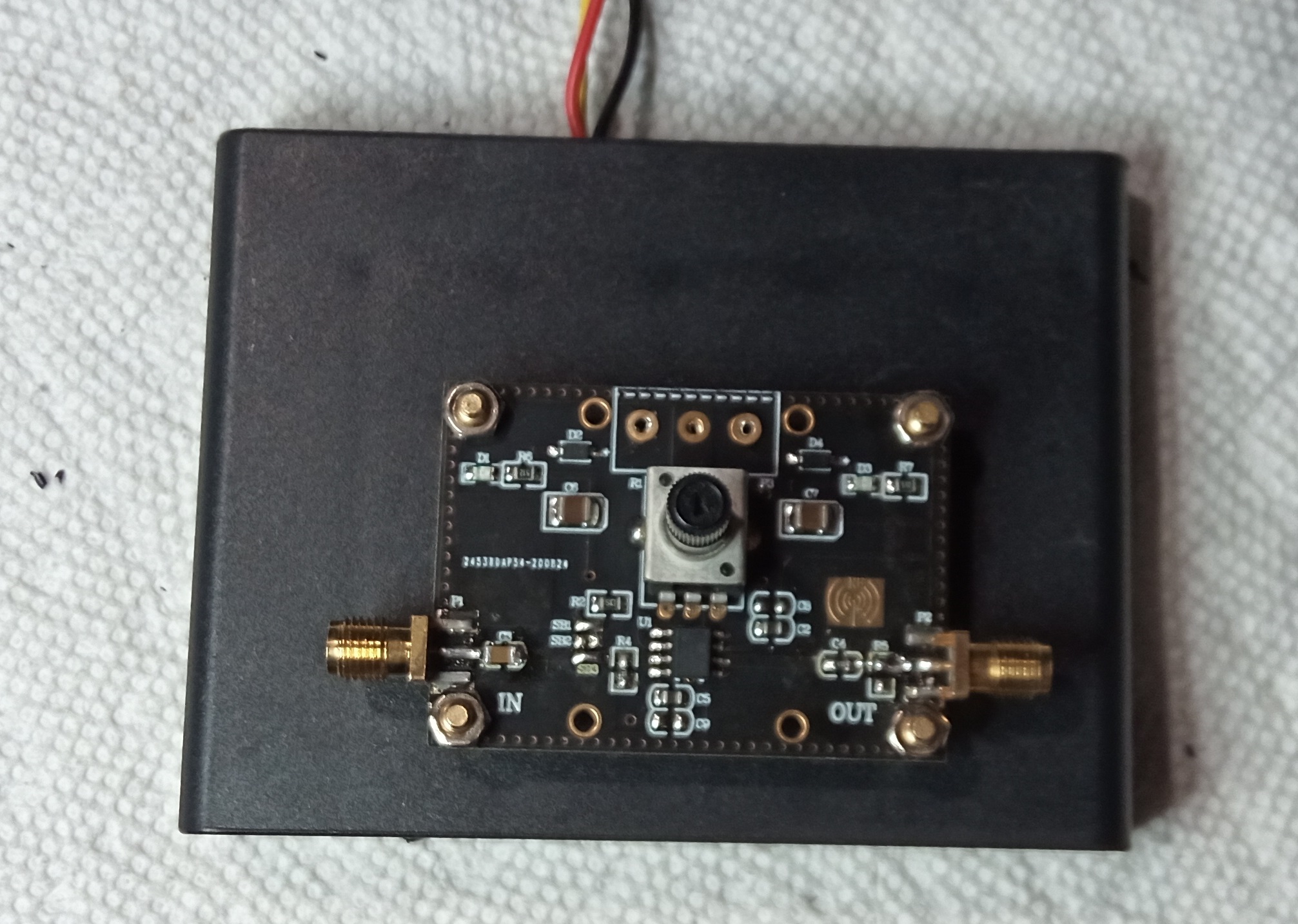
Here's a pre modification picture of the board, for reference: https://raw.githubusercontent.com/tandersn/cxadc-hw-mod/main/X_Pictures/opa657/th-532925870.jpg
0805 SMD components work well for this board. 0603 can be used easily too, though. 1206 can be made to work, but you have to pay extra care to make sure they are connected to the pads because they are a bit too big.
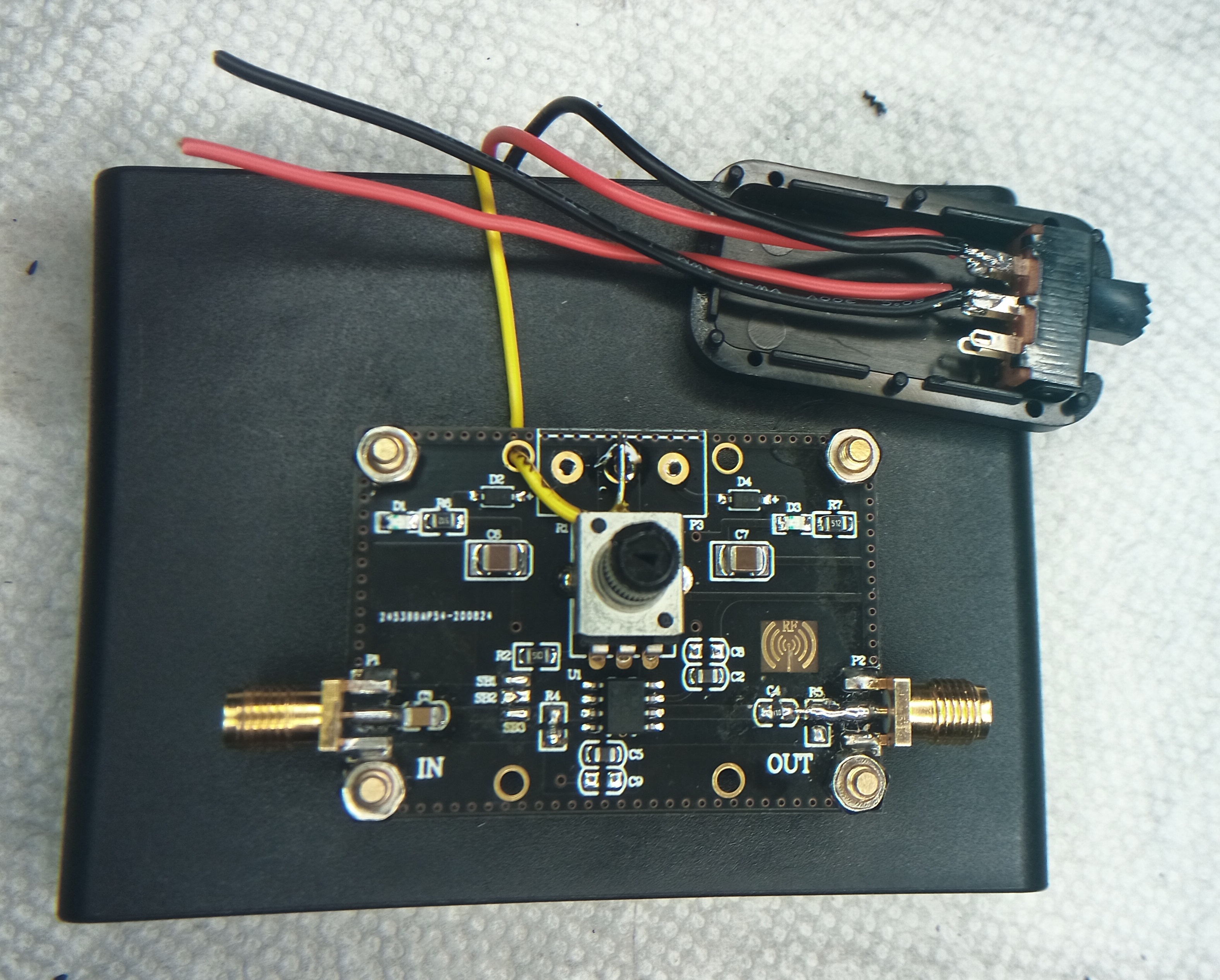
- Proceed to modify the amp board as notated in this picture:
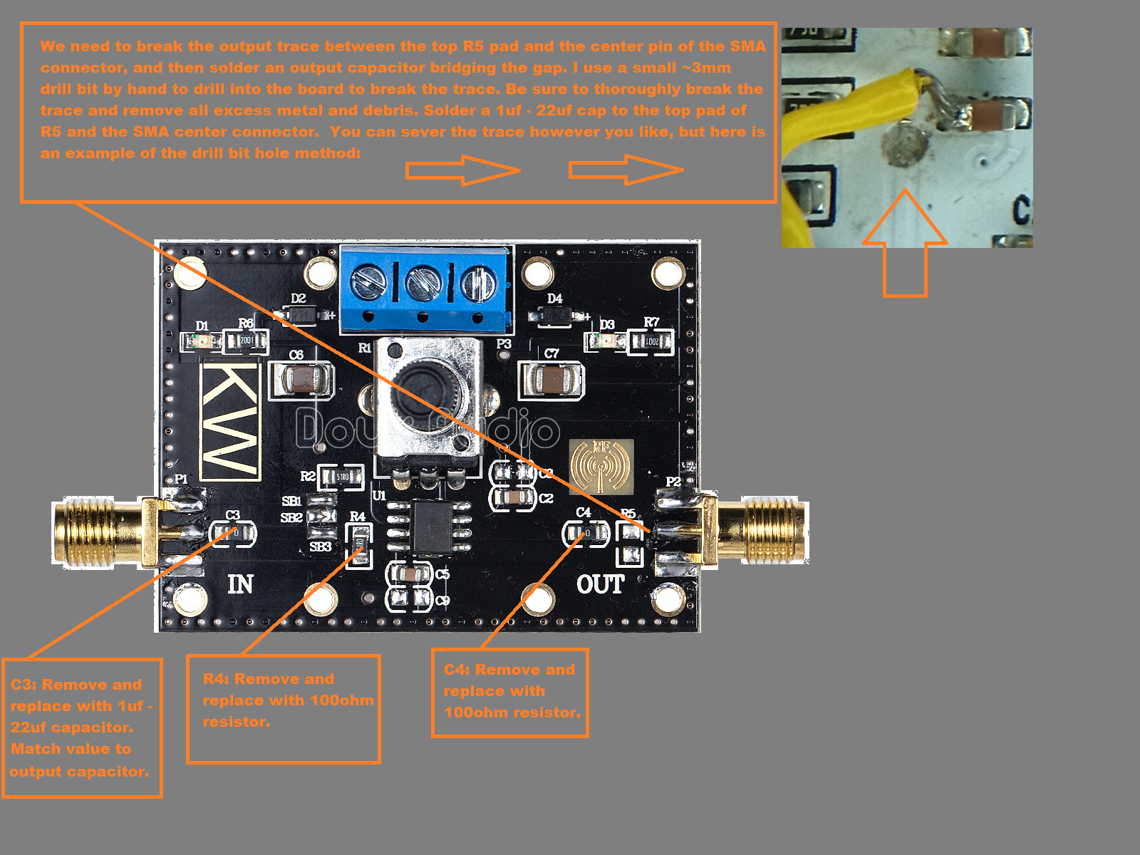
It is imperative that the output circuit be completely broken and jumpered properly with the capacitor. Clean it well, and inspect with magnifying glass. My initial setup did not include the outgoing capacitor, but on some players there was too much DC offset without it. You may try without that first with your player, as it is the most difficult part of modding the board. If you have too much DC offset in your captures, add it in.
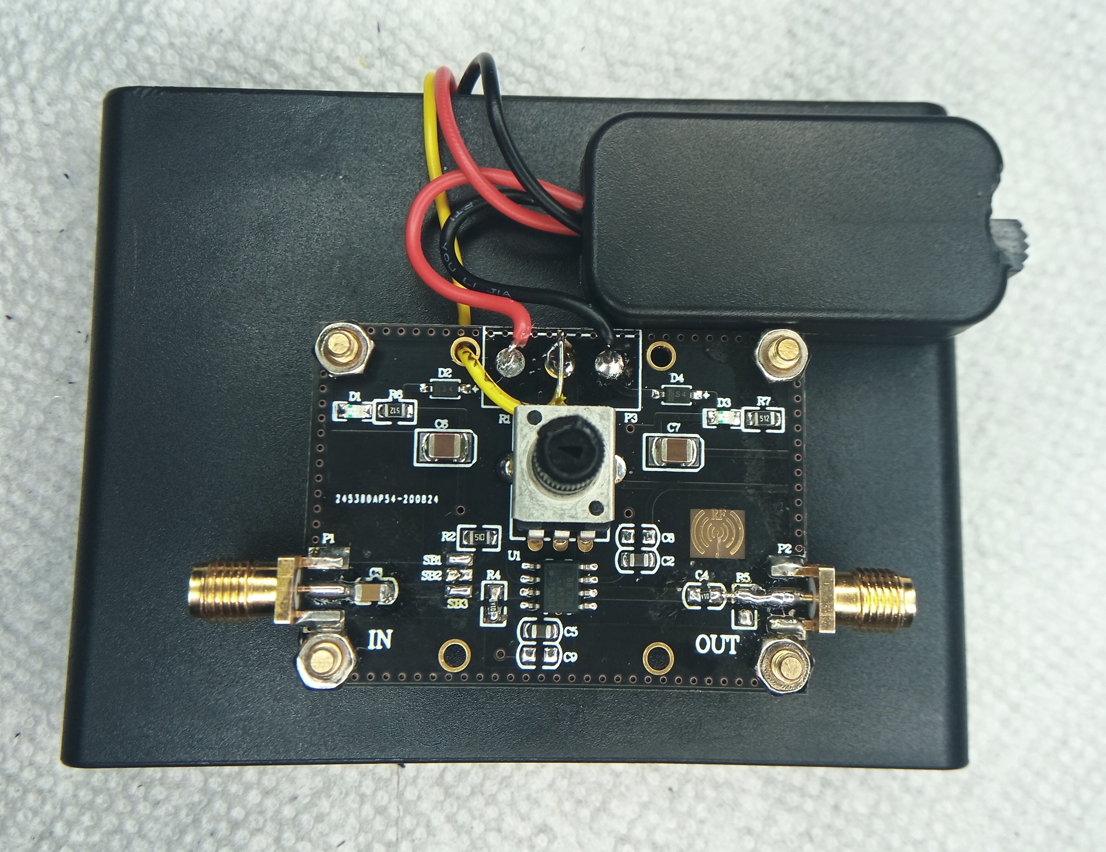
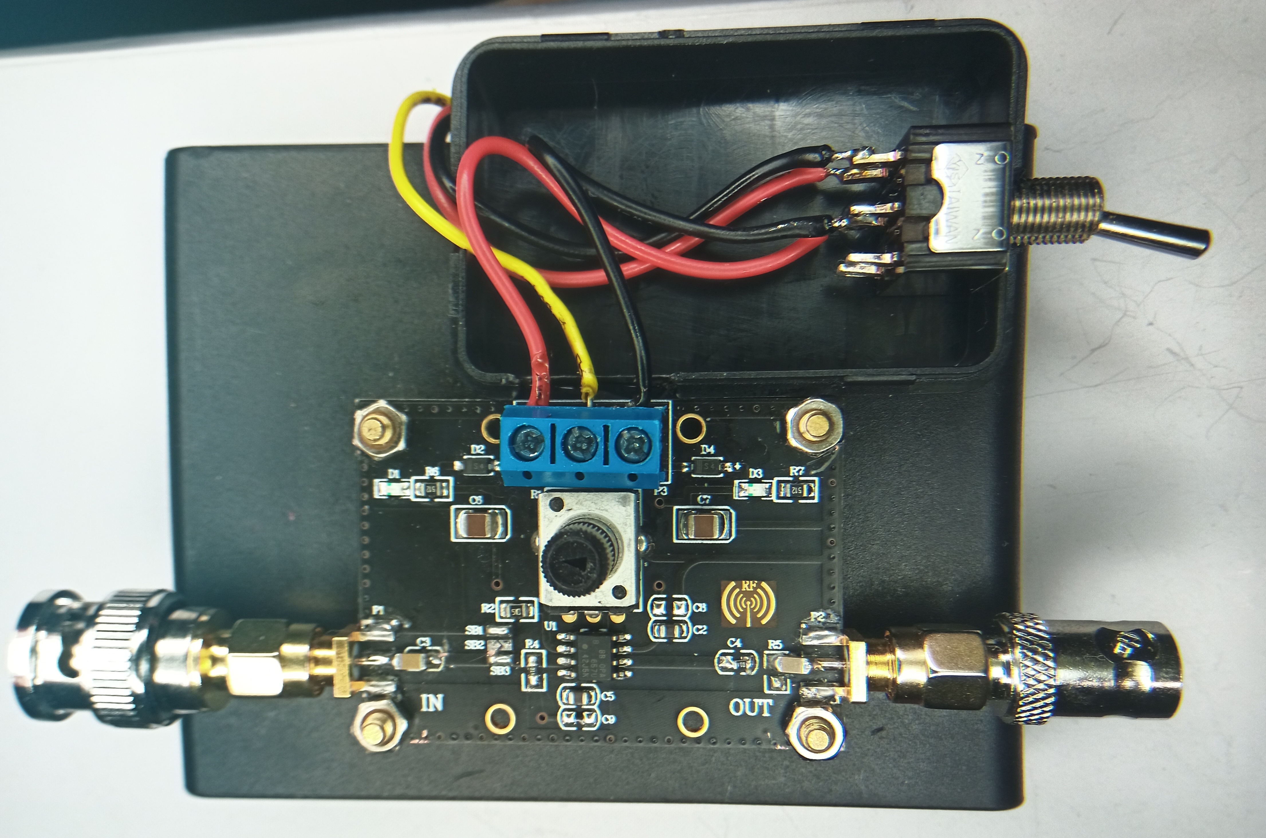
- Optional: remove the power supply block (blue in this picture) and solder the wires from the battery pack directly to it.
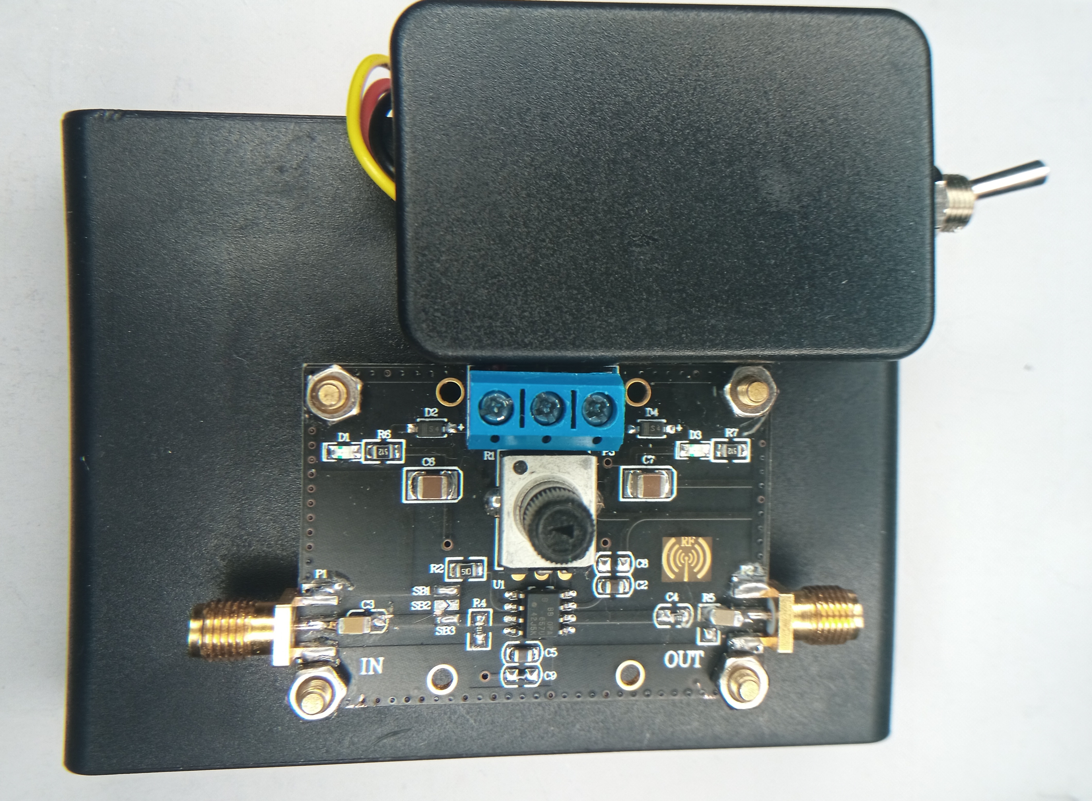
- After mods you should have something like this:

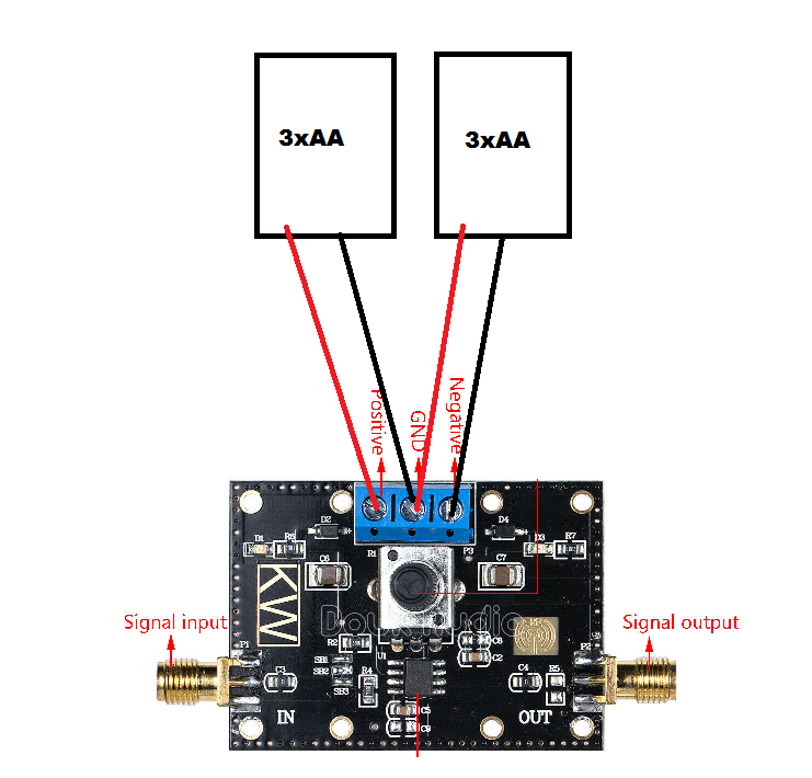
We need to add a center tap wire, so we can have a +4.5v and -4.5v with a center reference. I'll be incorporating a DPDT switch into my build. I wouldn't really consider this optional, but you could technically get away with taking the batteries out between each usage. A DPST switch would also work, but there seems to be a lot more selection of DPDT swtiches, and you just abandon the other side and use it as a DPST. The following is just an example of how you can do it. It's up to the reader to tailor it to the supplies they have on hand.
WARNING!!! Do not use an 8xAA battery holder with regular brand new AA batteries, the voltage will be too high. Well used regular AAs or rechargeable AAs have a lower voltage.
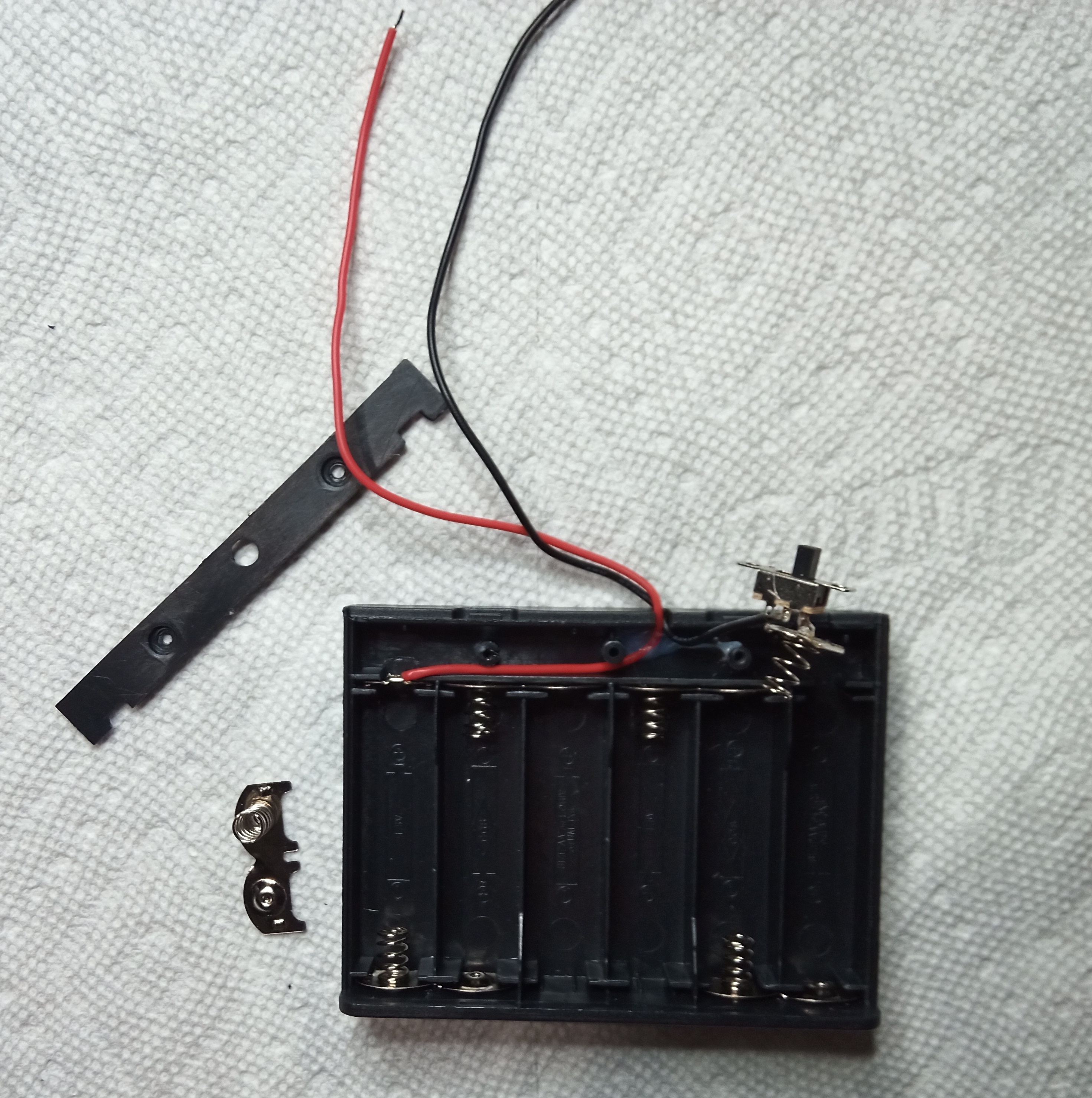
- Remove the battery cover to expose the 2 screws:
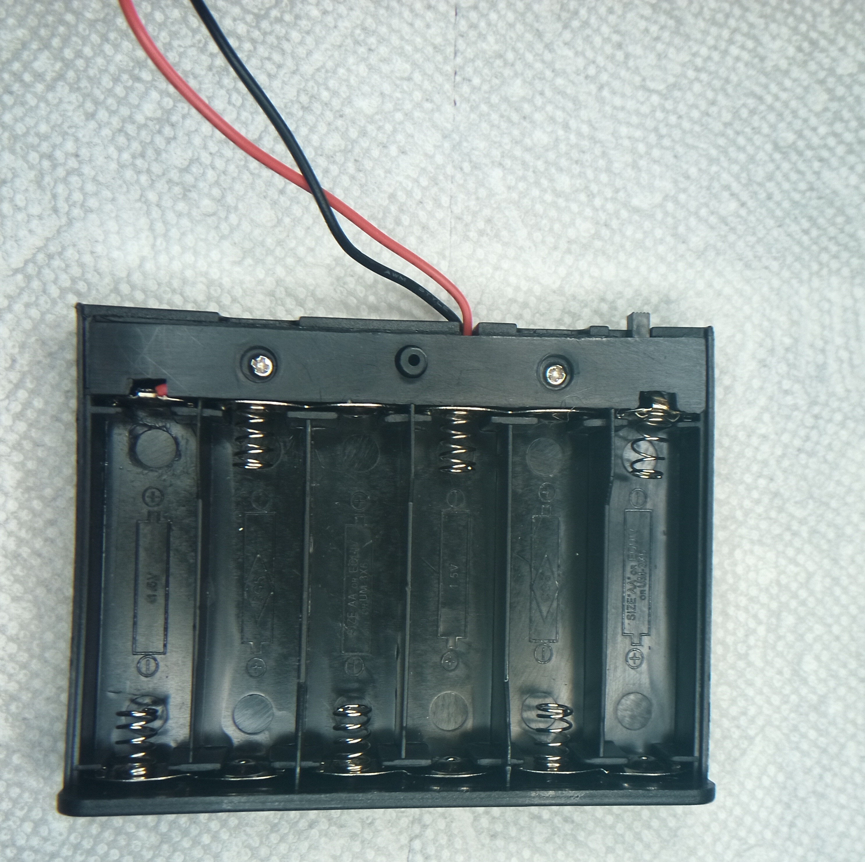
- Remove the battery ends for the one connected to the switch, and for the center batteries (image is for 6aa, for 8aa, it'd be on the top):
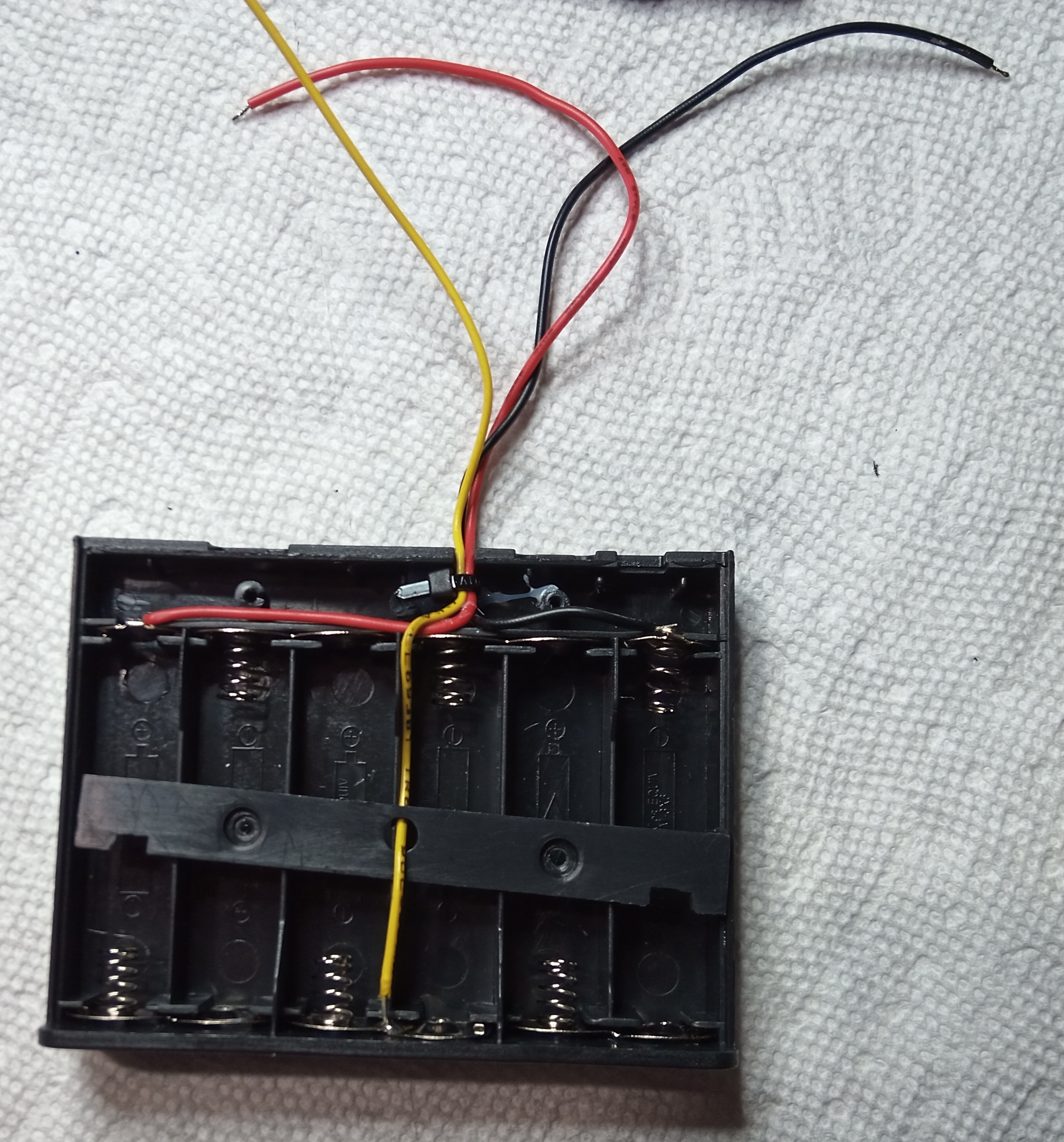
- Solder a wire to the center battery connector, use any color but red or black (yellow in my pics), so you can differentiate. Remove the switch and solder the black wire directly to the battery connector it was switching. For the examples in these pics, i broke the little plastic nub in the middle, and ran the wire through the hole of the cover. In subsequent mods, i've just made a little notch for the wire in the base. After that, zip tie the wires together:
- Reassemble:

CHECK YOUR VOLTAGES!! Before proceeding, insert the batteries and make sure you have 4.5v between the yellow wire and the red wire, and the yellow wire and the black wire. Double check this, it is very important.
If you don't create a solid fixed setup, the wires to involved in the power supply can break after repeated bending.
- Mark out holes in battery case and drill them out, ensuring the posts land in flat areas inside the battery holder, and so the amp will be offset to towards the bottom:
- Use mounting hardware that came with amp, or use old leftover computer motherboard mounting studs. Just need to make sure to use flat head screws to screw the studs on:
- If your not using a switch, just connect / solder the 3 wires to the amp board, the center tap wire goes to the center power point (see pics below).
In the following pictures, i'll show different switches and connecting with and without the power block. There's not much complexity here. Just solder the black and red wires to the same rows on your switch, and run the center wire straight through. If you don't know how DPDT switches work, may want to read up a little bit and look at some diagrams.
- Small DPDT switch, soldered directly to board:
- Larger DPDT switch, using amp board power block:
I just used some ordinary glue to glue the small box to the batter holder. Note that you could probably mount the small switch directly to the battery case utilizing the void inside where the original switch was.
The two 3xAA holders with the switches incorporated are the easiest to set up. You literally just connect the wires and your done. It can be fragile, as when the items are not physically connected together, the wires will break after a time, being moved a lot. It's also harder to move around. If you plan on leaving your amp setup in one place for long periods of time though, this actually works just fine.
- Simply wire the 2 battery holders as shown here, and use both switches to turn on and off:
Possibly there is some way to make a neat little package with the two 3xAA holders as well. Use your imagination!