Mixed Signal SOC Design Hackathon
• Abstract
  • Reference Circuit Diagram
  • Reference Waveform
  • Circuit Details
  • Software Used
    • esim
    • NgSpice
    • Makerchip
    • Verilator
  • Circuit Diagram in esim
  • Verilog Code
  • Makerchip
  • Makerchip plots
  • Netlists
  • NgSpice Plots
  • Steps to run generate NgVeri Model
  • Steps to run this project
  • Acknowlegdements
  • References
Abstract This paper contains implementation of 2-bit ripple upcounter with 555 timer Astable multivibrator as clock circuit. The most widely used application of ripple up counter is to act as an frequency divider circuit so that signal's high frequency can be reduced to usable value for low speed circuits.
Reference Circuit Diagram
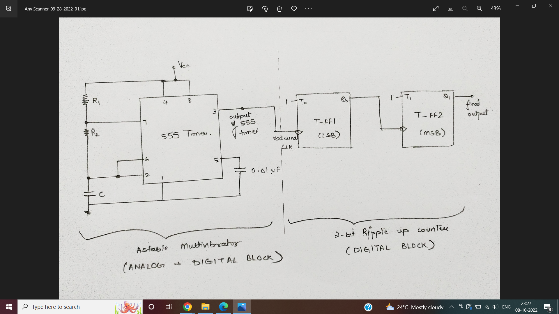 Fig 1- circuit diagram of the circuit to be implemented
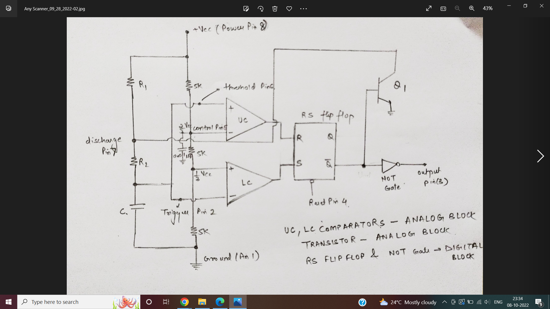 Fig 2- 555 timer Astable multivibrator for clock generation
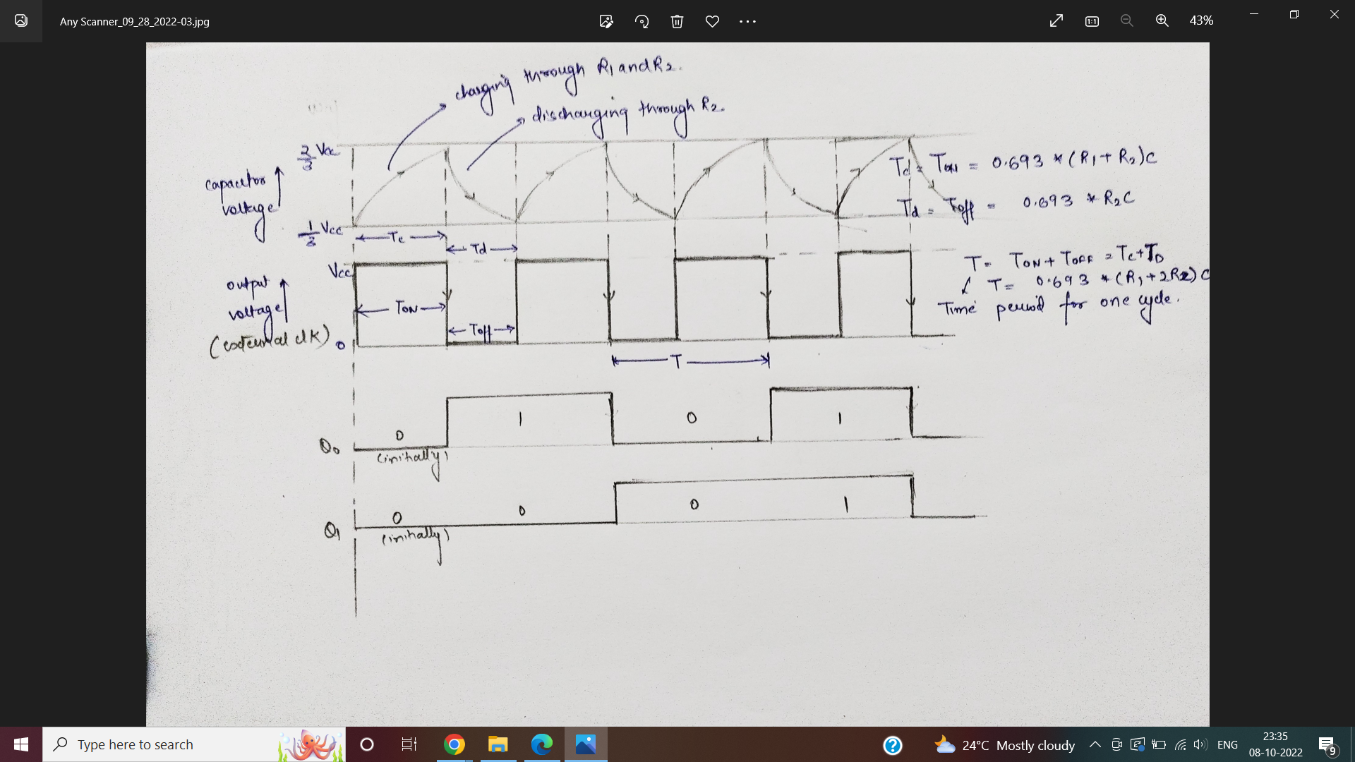
Reference Waveform
Circuit Details the mixed-signal circuit design implementation for the circuit shown in figure1 is explained as below:
- An astable multivibrator is used for clock generation which is given as external clock input to the 2-bit ripple Up- counter( i.e., this input is given to the LSB T-flip flop of the counter). The 555 timer circuitry (shown in figure2) is designed from scratch using analog circuitry block consistingo f comparators & transistors and digital circuitry block consisting of SR flip flop & NOT gate. The rectangular waveform generated as an output (resulting in output frequency, Fclk) due to charging and discharging of capacitor (capacitor voltage swinging between 2Vcc/3 and Vcc/3). During charging period, output is HIGH(I.e., logic ‘1’) and during discharging period, output is LOW(I.e., logic ‘0’). As this 555 timer configuration automatically interchanges its state between logic HIGH and logic LOW, therefore it is also known as free running multivibrator. The various other applications of 555 timer astable multivibrator includes square waveform generator, pulse position modulation and frequency modulation.
- The ripple counter shown in figure 1 is completely implemented as a digital block. In ripple counter, output of one flip flop acts as an clock input to the next serially connected flip flop (hence, clock pulses ripples through the circuit). Here all the flip flops are configured to be operating in toggle mode. When this rectangular waveform (external clock) is given to serially connected T- flip flops then in this ripple counter, the output of 1 st T-flip flop(LSB) is given as clock input to 2 nd T-flip flop(MSB). Both the T-flip flops are changing their state at falling edge of their corresponding clocks. Then the frequency obtained at the output of 2 nd T-flip flop( I.e., at Q1) is Fclk/4. Here Fclk is the frequency of the output from astable multivibrator and ‘4’ indicates the number of unique states obtained using this 2- bit ripple up counter.
Software Used
eSim
It is an Open Source EDA developed by FOSSEE, IIT Bombay. It is used for electronic circuit simulation. It is made by the combination of two software namely NgSpice and KiCAD. For more details refer: https://esim.fossee.in/home

NgSpice
It is an Open Source Software for Spice Simulations. For more details refer: http://ngspice.sourceforge.net/docs.html

Makerchip
It is an Online Web Browser IDE for Verilog/System-verilog/TL-Verilog Simulation. Refer https://www.makerchip.com/

Verilator
It is a tool which converts Verilog code to C++ objects. Refer: https://www.veripool.org/verilator/
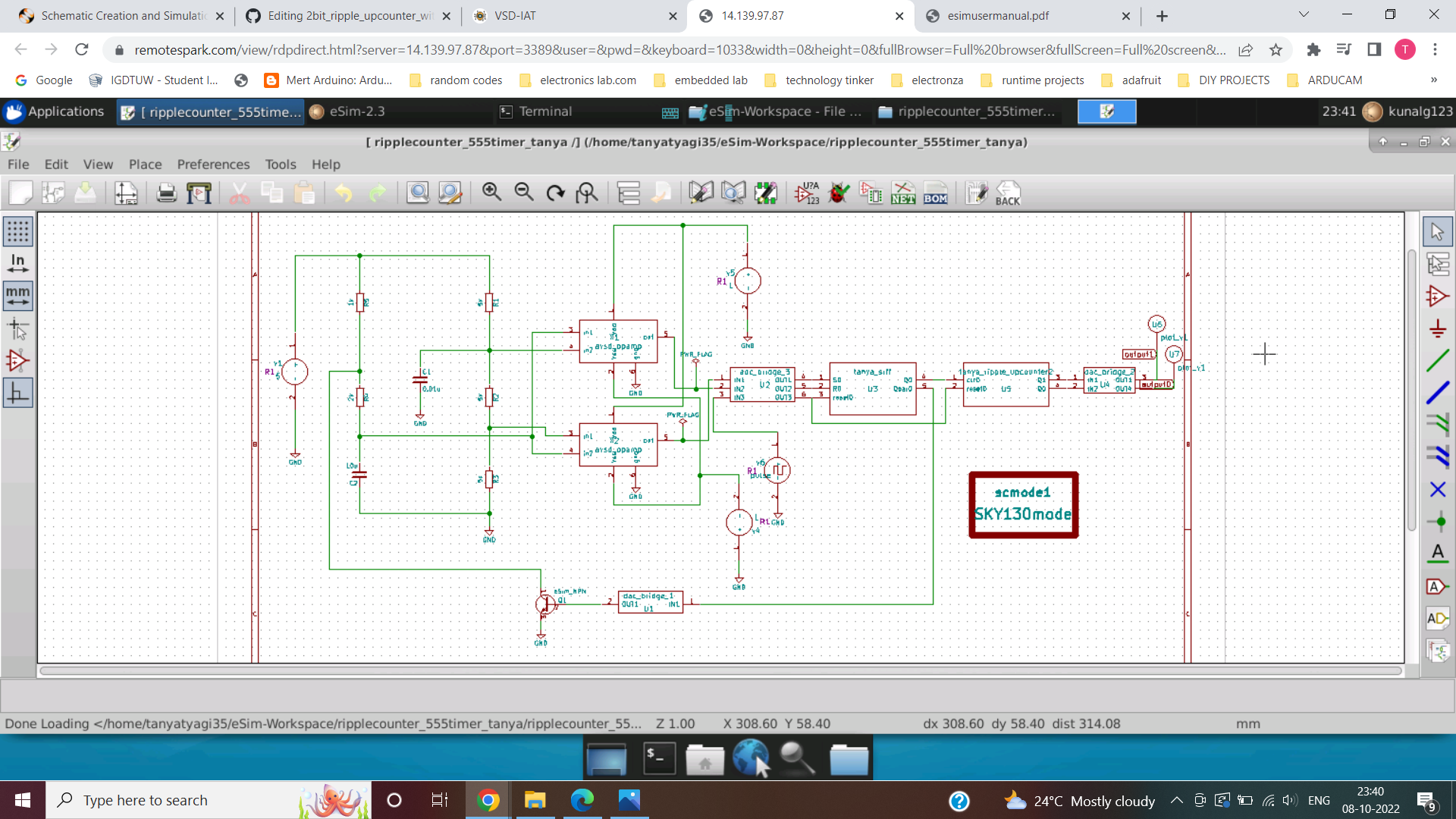
Circuit Diagram in eSim
Verilog Code for 2bit ripple upcounter

//verilog code for T-flip flop module

module tff(input clk_n, input reset_p, output Q);

	wire D;
	dff d0(D, clk_n, reset_p, Q);
	not n1(D, Q);  // where D is the output and Q is the input
endmodule

// verilog code for D-flip flop module

module dff(D, clk_n, reset_p, Q);

	input D, clk_n, reset_p;
	output reg Q;

	always @(posedge reset_p or negedge clk_n)
	if (reset_p)
		Q<=1'b0;
	else
		Q<=D;

endmodule

module tanya_ripple_upcounter2(clk, reset, Q);

	input clk, reset;
	output [1:0] Q;

	tff tO(clk, reset, Q[0]);  //LSB T-flip flop
	tff t1(Q[0], reset, Q[1]);  //MSB T-flip flop

endmodule
verilog code for RS flip flop of 555 timer

//verilog code for SR flip flop

module tanya_srff(S, R, reset, Q, Qbar);

	input S, R, reset;
	output reg Q, Qbar;

	always @(*)
	begin
		if (reset)
		begin
			Q<=1'b0;
			Qbar<=1'b1;
		end

		else
		begin
			if(S==0 && R==0)
			begin
				Q<=Q;
				Qbar<=Qbar;
			end
			else if(S==0 && R==1)
			begin
				Q<=1'b0;
				Qbar<=1'b1;
			end
			else if(S==1 && R==0)
			begin
				Q<=1'b1;
				Qbar<=1'b0;
			end
			else
			begin
				Q<=1'bx;
				Qbar<=1'bx;
			end
		end
	end
endmodule
Makerchip code for ripple upcounter

\TLV_version 1d: tl-x.org
\SV
/* verilator lint_off UNUSED*/  /* verilator lint_off DECLFILENAME*/  /* verilator lint_off BLKSEQ*/  /* verilator lint_off WIDTH*/  /* verilator lint_off SELRANGE*/  /* verilator lint_off PINCONNECTEMPTY*/  /* verilator lint_off DEFPARAM*/  /* verilator lint_off IMPLICIT*/  /* verilator lint_off COMBDLY*/  /* verilator lint_off SYNCASYNCNET*/  /* verilator lint_off UNOPTFLAT */  /* verilator lint_off UNSIGNED*/  /* verilator lint_off CASEINCOMPLETE*/  /* verilator lint_off UNDRIVEN*/  /* verilator lint_off VARHIDDEN*/  /* verilator lint_off CASEX*/  /* verilator lint_off CASEOVERLAP*/  /* verilator lint_off PINMISSING*/    /* verilator lint_off BLKANDNBLK*/  /* verilator lint_off MULTIDRIVEN*/    /* verilator lint_off WIDTHCONCAT*/  /* verilator lint_off ASSIGNDLY*/  /* verilator lint_off MODDUP*/  /* verilator lint_off STMTDLY*/  /* verilator lint_off LITENDIAN*/  /* verilator lint_off INITIALDLY*/

//Your Verilog/System Verilog Code Starts Here:
//verilog code for T-flip flop module

module tff(input clk_n, input reset_p, output Q);

	wire D;
	dff d0(D, clk_n, reset_p, Q);
	not n1(D, Q);  // where D is the output and Q is the input
endmodule

// verilog code for D-flip flop module

module dff(D, clk_n, reset_p, Q);

	input D, clk_n, reset_p;
	output reg Q;

	always @(posedge reset_p or negedge clk_n)
	if (reset_p)
		Q<=1'b0;
	else
		Q<=D;

endmodule

//verilog code for 2bit ripple upcounter module

module tanya_ripple_upcounter2(clk, reset, Q);

	input clk, reset;
	output [1:0] Q;

	tff tO(clk, reset, Q[0]);  //LSB T-flip flop
	tff t1(Q[0], reset, Q[1]);  //MSB T-flip flop

endmodule

//Top Module Code Starts here:

	module top(input logic clk, input logic reset, input logic [31:0] cyc_cnt, output logic passed, output logic failed);
		logic  [1:0] Q;//output
//The $random() can be replaced if user wants to assign values
		tanya_ripple_upcounter2 tanya_ripple_upcounter2(.clk(clk), .reset(reset), .Q(Q));

\TLV
//Add \TLV here if desired
\SV
endmodule
Makerchip code for 555timer SR flip flop
\TLV_version 1d: tl-x.org
\SV
/* verilator lint_off UNUSED*/  /* verilator lint_off DECLFILENAME*/  /* verilator lint_off BLKSEQ*/  /* verilator lint_off WIDTH*/  /* verilator lint_off SELRANGE*/  /* verilator lint_off PINCONNECTEMPTY*/  /* verilator lint_off DEFPARAM*/  /* verilator lint_off IMPLICIT*/  /* verilator lint_off COMBDLY*/  /* verilator lint_off SYNCASYNCNET*/  /* verilator lint_off UNOPTFLAT */  /* verilator lint_off UNSIGNED*/  /* verilator lint_off CASEINCOMPLETE*/  /* verilator lint_off UNDRIVEN*/  /* verilator lint_off VARHIDDEN*/  /* verilator lint_off CASEX*/  /* verilator lint_off CASEOVERLAP*/  /* verilator lint_off PINMISSING*/    /* verilator lint_off BLKANDNBLK*/  /* verilator lint_off MULTIDRIVEN*/   /* verilator lint_off WIDTHCONCAT*/  /* verilator lint_off ASSIGNDLY*/  /* verilator lint_off MODDUP*/  /* verilator lint_off STMTDLY*/  /* verilator lint_off LITENDIAN*/  /* verilator lint_off INITIALDLY*/
//Your Verilog/System Verilog Code Starts Here:
//verilog code for SR flip flop

module tanya_srff(S, R, reset, Q, Qbar);

	input S, R, reset;
	output reg Q, Qbar;

	always @(*)
	begin
		if (reset)
		begin
			Q<=1'b0;
			Qbar<=1'b1;
		end

		else
		begin
			if(S==0 && R==0)
			begin
				Q<=Q;
				Qbar<=Qbar;
			end
			else if(S==0 && R==1)
			begin
				Q<=1'b0;
				Qbar<=1'b1;
			end
			else if(S==1 && R==0)
			begin
				Q<=1'b1;
				Qbar<=1'b0;
			end
			else
			begin
				Q<=1'bx;
				Qbar<=1'bx;
			end
		end
	end
endmodule


//Top Module Code Starts here:
	module top(input logic clk, input logic reset, input logic [31:0] cyc_cnt, output logic passed, output logic failed);
		logic  S;//input
		logic  R;//input
		logic  Q;//output
		logic  Qbar;//output
//The $random() can be replaced if user wants to assign values
		assign S = 1'b1;
		assign R = 1'b0;
		tanya_srff tanya_srff(.S(S), .R(R), .reset(reset), .Q(Q), .Qbar(Qbar));

\TLV
//Add \TLV here if desired
\SV
endmodule
Makerchip plots for ripple upcounter

Makerchip plots for 555timer SR flip flop

Acknowlegdements 1.FOSSEE, IIT Bombay 2.Kunal Ghosh, Co-founder, VSD Corp. Pvt. Ltd. - kunalpghosh@gmail.com 3.Sumanto Kar, eSim Team, FOSSEE
References
- https://circuitdigest.com/electronic-circuits/555-timer-astable- multivibrator-circuit-diagram
- https://www.electronicshub.org/astable-multivibrator-using-555- timer/
- https://www.electricaltechnology.org/2018/05/digital-asynchronous- counter-ripple-counter-types.html
- https://www.circuitstoday.com/555-timer-astable-multivibrator
- https://github.com/vinisha2410/3bit_Binary_Counter_With_Astable_Multivibrator_As_Clock_Circuit