
In my hand is a 4-Digit 7-Segment display module. The heart of this module is an inexpensive Serial LED Driver from Titan Micro Electronics called the TM1637.
In this tutorial, I am going to show you guys how to control the TM1637 4-Digit 7-Segment displays using an Arduino. If you want to displays sensor data, temperature and humidity, or want to design a clock, timer or counter, you will need this 4-Digit Seven-Segment Display.
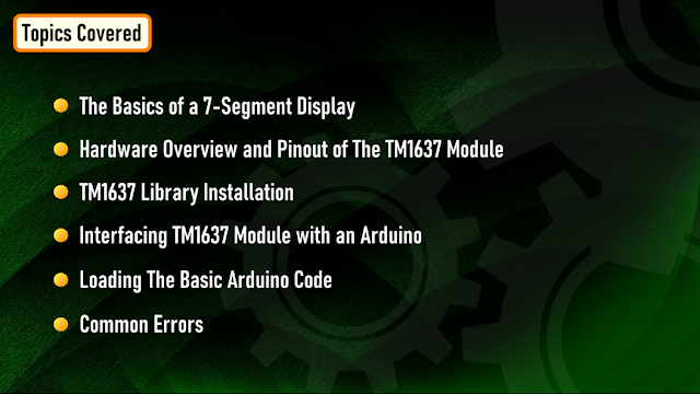
In this tutorial we are going to talk about: The Basics of a 7-Segment Display Hardware Overview and Pinout of The TM1637 Module TM1637 Library Installation Interfacing TM1637 Module with an Arduino Loading The Basic Arduino Code (that comes with the TM1637 library)
Then we will have a look at some of these quick examples: Example 1: Displaying String and a Number Example 2: Displaying Scrolling and Blinking Text Example 3: Creating a 4 Digit Counter Example 4: Displaying Temperature & Humidity using DHT11/DHT22 Example 5: Creating an Arduino Based Digital Clock
And finally we will have a look at some common errors.
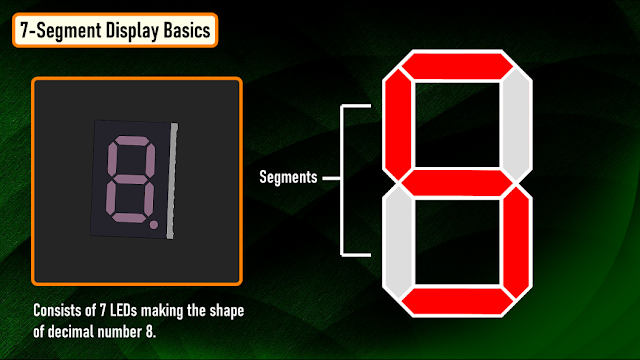
A 7-Segment Displays consists of 7 LEDs making the shape of decimal number 8. These LEDs are called segments, because when they light up, each segments contributes in the formation of part of a decimal or hex digit.
These individual segments are labeled from ‘a’ to ‘g’ representing each individual LED. By setting a particular segment HIGH or LOW, a desired character pattern can be generated.
The module comes with 4 right angle male pin headers. I find it a bit annoying to have the pin headers on the top side of the board. However, you can always unsolder and put them at the bottom of the board.
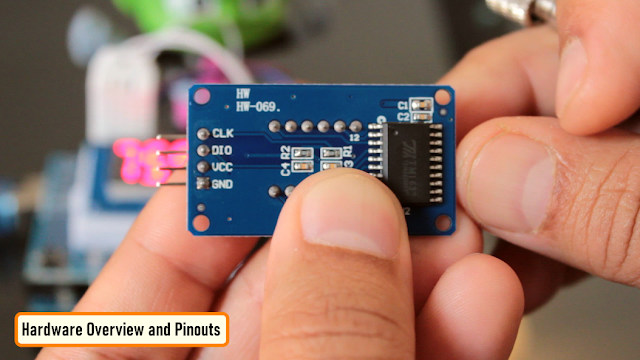
Now lets have a look at the GPIO pins: CLK - is the clock input pin. You can connect it to any digital pin of an Arduino. DIO - is the Data I/O pin. This can also connect to any digital pin of an Arduino. VCC - Connects to 3.3V to 5V power supply. GND - is the ground pin.
CLK and DIO pins can be connected to any digital pin of an Arduino. This gives us an opportunity to hook up a lot of these modules to an Arduino, as long as each instance has a pin pair of its own. When writing the code, we just need to specify the pin pair and then just go ahead and use them in your project.
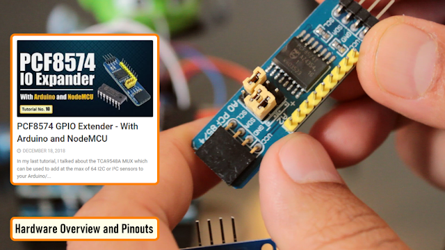
If you run out of pins on your Arduino board you can use a GPIO Pin Extenders like the PCF8574. Please check out my tutorial on the Extender module, the link is in the description below. PCF8574 GPIO Extender: https://diyfactory007.blogspot.com/2018/12/pcf8574-gpio-extender-with-arduino-and.html
The module has 4 x 0.36 segment 7-Segment Displays and a ‘colon’ at the center for creating clock or time-based projects.
A bare four digit 7-Segment Displays usually requires 12 connection pins but the TM1637 LED Driver removes the need of the extra wiring for the 7-Segments and the entire setup can be controlled just by using 2 wires (DIO and CLK) and two more for power reducing the total wires to 4.
These modules communicate with the processor using "I2C-like protocol". The implementation is pure software emulation and doesn't make use of any special hardware (other than GPIO pins). The module operates between 3.3v to 5v with a current consumption of 80ma and allows adjusting the brightness of the LEDs at the software level. They are available in few different colors.
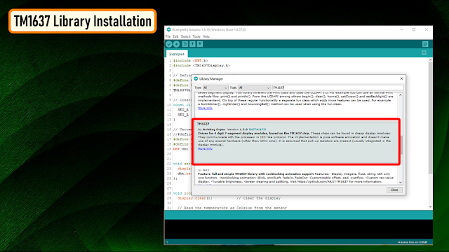
There are many libraries available for the TM1637 module. For this tutorial, we are going to use the "TM1637Display Library" written by "Avishay Orpaz". You can download the library using the library manager or from Github, the link is in the description below.
To install the library using "Library Manager", navigate to Sketch > Include Library > Manage Libraries… Search for "TM1637" and look for the one by "Avishay Orpaz". Hit the "Install" button to install the library on your device.
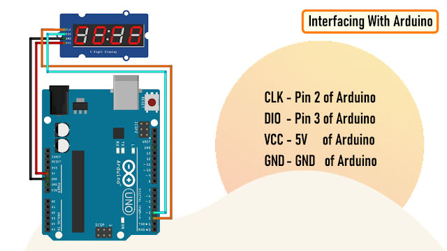
Hooking up the TM1637 module to an Arduino is very easy. You just need to connect four wires: 2 for power and other 2 for controlling the display. You can connect the VCC of the module to either 3.3v or 5v pin of the Arduino. So, connect: CLK - Pin 2 of Arduino DIO - Pin 3 of Arduino VCC - 5V of Arduino GND - GND of Arduino As previously advised, you can use any pin combination for the CLK and DIO on the Arduino board. Just make sure you change the pin numbers in the code to reflect the change of wiring.
So far, based on my experience I have only found one disadvantage. This module is unable to display floating points or dots between numbers. However, you can use the "HT16K33 module" for displaying floating points.
Before going ahead, lets have a look at the example that comes with the TM1637 Library. Navigate to File > Examples > TM1637 and load the "TM1637Test" example.
The sketch starts by including the "TM1637Display.h" library. Then it defines the CLK and the DIO pins that will be used to connect the TM1637 display. In this example Pin-2 of Arduino is used for CLK and Pin-3 for DIO.
#include <TM1637Display.h>
#define CLK 2
#define DIO 3
Next, you need to create a new instance of the "TM1637Display" class by passing the CLK and the DIO Pin values to it.
TM1637Display display(CLK, DIO);
Then, the code shows us 2 ways of displaying data on the individual segments by creating arrays of texts.
a. 1st by passing "hexadecimal numbers" to the individual displays

	uint8_t data[] = {0xff, 0xff, 0xff, 0xff};

	Passing "0xff" to all the 4 displays will turn them all ON, and passing "0x00" will turn them all OFF.
	Using the "display.encodeDigit()" function you can display digits between 1 and 15.

	data[0]= display.encodeDigit(15); // This will display F___ on the display [0b01110001 = F]
	display.setSegments(data);

	This will display F___ on the display.

b. 2nd by individually specifying the segments that you want to turn on.
	The below creates an array that sets the individual segments values and displays "dOnE" on the display.

	uint8_t done[] = {
	  SEG_B | SEG_C | SEG_D | SEG_E | SEG_G,           // d
	  SEG_A | SEG_B | SEG_C | SEG_D | SEG_E | SEG_F,   // O
	  SEG_C | SEG_E | SEG_G,                           // n
	  SEG_A | SEG_D | SEG_E | SEG_F | SEG_G            // E
	};
Now, to display these arrays, you need to pass them to the "display.setSegments()" function.
display.setSegments(data); // Will turn off all LEDs
display.setSegments(done); // Will display "dOnE"

The setSegments function accepts 3 arguments

setSegments(data[], length, position);

Data     = The data to display
Length   = number of digits to be updated (0–4). Ex. for "dOnE", it will be 4, for the "°C" it will be 2.
Position = determines the position from which you want to print (0-leftmost, 3-rightmost).
Remember, the LEDs once turned on stays on until they are turned off. So, you always have to clear the previous value before displaying the new one. This can be done by passing 4 lots of 0xffto the "display.setSegments()" function or by using "display.clear()" function.
uint8_t data[] = {0xff, 0xff, 0xff, 0xff};
display.setSegments(data);
The brightness of the display can be adjusted using the "setBrightness()" function. The function accepts values between 0 (lowest) to 7 (highest).
display.setBrightness(3); // Sets the brightness level to 3
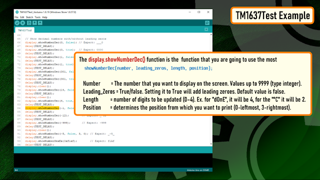
The "display.showNumberDec()" function is the function that you are going to use the most to display numbers on the module. The first argument is a number that you want to display on the screen. The rest of the arguments are all optional.
Syntax:
	showNumberDec(number, leading_zeros, length, position);

	Number        = The number that you want to display on the screen. Values up to 9999 (type integer).
	Leading_Zeros = True/false. Setting it to True will add leading zeroes. Default value is false.
	Length   	  = number of digits to be updated (0–4). Ex. for "dOnE", it will be 4, for the "°C" it will be 2.
	Position 	  = determines the position from which you want to print (0-leftmost, 3-rightmost).
Example:
	display.showNumberDec(1,false) 		// Displays ___1
	display.showNumberDec(1,false,1,0)  // Displays 1___
	display.showNumberDec(1,false,1,2) 	// Displays __1_
	display.showNumberDec(10,false,2,0) // Displays 10__

For the rest of the examples, I am going to use this template to write the code. I will only show you guys the bit which is different in each code.

In this example you can see letter "TEST" and a randomly generated number is alternating and getting displayed on the screen.
To display the letter TEST, I am first clearing the screen and then lighting up the individual segments to display the characters.
To display a number, I am first generating a random number between 0 and 9999 and then displaying it using the "display.showNumberDec()" function.

Now, to display a scrolling text, I am incrementing the position of the text by 1 and then displaying it from the new position. You need to pad the display with any character or it will end up showing random characters on the display.
Blinking a text is super easy. All you have to do is display the text, add a delay, clear the screen and then again add a delay before displaying the text again.
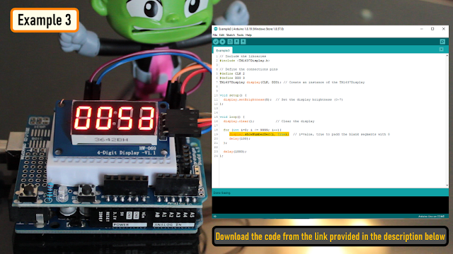
To display a counter, I am looping from 0 to 9999 and displaying the incremented value every time on the 7-Segments.
You can also add a push button switch to start and stop the counter.
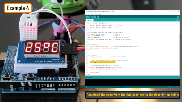
Connect the OUT pin of the DHT11/DHT22 sensor to Pin-5 of the Arduino.
Then in the code include the "DHT.h" library and define the DHTPIN and the DHTTYPE. Next, create a DHT object and in the setup section initialize the DHT sensor using the "dht.begin()" function.
Next in the loop section read the sensor data using the "dht.readTemperature()" function and display it on the 7-Segments.
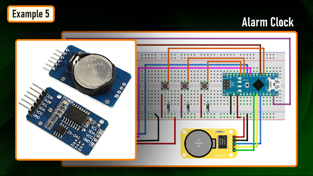
You can also create an alarm clock using either the DS3231 or DS1302 RTC Module and display the data using this TM1637 module. I will cover that in full details in my next video.

Now lets have a look at some off the common errors: Display showing parts of the previous data. You always have to clear the previous value before displaying the new one. You can either use: display.clear(); or uint8_t data[] = {0xff, 0xff, 0xff, 0xff}; display.setSegments(data);
Display data going out of the display or showing partially Check the positioning of the display data. setSegments(data[], length, position);
These are few of the issues that I came across while playing around with these displays. Do comment and let me know if you have any more to add to the list.
Thanks again for checking my post. I hope it helps you. If you want to support me subscribe to my YouTube Channel: https://www.youtube.com/user/tarantula3
Links:
Video: Video Link https://youtu.be/Ob9mrq_Lj9k
Full Blog Post: Blog Post https://diyfactory007.blogspot.com/2022/11/TM1637-Digit-Display.html
Datasheet: Download https://github.com/tarantula3/TM1637-Digit-Display/blob/main/Datasheet.pdf
Schema: Download https://github.com/tarantula3/TM1637-Digit-Display/blob/main/Sketch.fzz
TM1637Display Library: Download https://github.com/avishorp/TM1637
Thingiverse : Download https://github.com/tarantula3/TM1637-Digit-Display/blob/main/TM1637_HW-069.stl
PCF8574 GPIO Extender: Blog Post https://diyfactory007.blogspot.com/2018/12/pcf8574-gpio-extender-with-arduino-and.html
Code:
Example1: Download https://github.com/tarantula3/TM1637-Digit-Display/blob/main/Example1.zip
Example2: Download https://github.com/tarantula3/TM1637-Digit-Display/blob/main/Example2.zip
Example3: Download https://github.com/tarantula3/TM1637-Digit-Display/blob/main/Example3.zip
Example4: Download https://github.com/tarantula3/TM1637-Digit-Display/blob/main/Example4.zip
TM1637Test: Download https://github.com/tarantula3/TM1637-Digit-Display/blob/main/TM1637Test.zip
Template: Download https://github.com/tarantula3/TM1637-Digit-Display/blob/main/Template.zip
Support My Work:
BTC: 15cNh9hup8jidCVPwa1DTcxeoh2FPijVrX
LTC: LbquH9Ku78vHtcm3LZnWXpD1JQWdKzeV4v
DOGE: DEB2QBAihnBRhGsaB8P7kz559TDiucQhX6
ETH: 0x5d8c9ba0e54d8354d4af81871db26daa190d2194
BAT: 0x939aa4e13ecb4b46663c8017986abc0d204cde60
LBC: bZ8ANEJFsd2MNFfpoxBhtFNPboh7PmD7M2
COS: bnb136ns6lfw4zs5hg4n85vdthaad7hq5m4gtkgf23 Memo: 572187879
BNB: 0x5d8c9ba0e54d8354d4af81871db26daa190d2194
Thanks, ca again in my next tutorial.