Teapot BWLR3D is an Asset Tracker and Environmental Sensor with Solar Energy Harvesting. The device is capable of sensing temperature, humidity, air pressure, air quality, light intensity using the on-board BME688 plus VEM7700, and calculate device's AHRS using the LSM6DSOX as accelerometer and gyrometer with LIS3MDL as magnetometer. Equiped with low-power L86-M33 GNSS module, the device is capable to locate itself anywhere in the world. With STM32WLE MCU as it's core and AEM10941 for solar charging, the device is capable ultra-low power operation with the possibility of indefinite battery-life by utilizing the solar charging capability.
Teapot BWLR3D is part of Teapot open-hardware project.
- The 1KM range is based on AERQ - Air Quality Monitoring design, but have not been tested on this device yet
- The position of the BME688 sensor on the board might not be the most efficient
- The position of the LIS3MDL sensor might get interference from the surrounding components and the provided magnetic case does interfere with the sensor.
- Develop code to read sensor and send data when movement is detected. LSM6DSOX can be set to ultra-low power mode and set to wake MCU when movement is detected, all other sensors needs to be in power-down mode.
- Change
SW4wiring from GND to 3V3, to allow booting to STM32WLE USART Bootloader. This enable the user to flash the RAK3172 module using STM32CubeProgrammer without ST-Link.
- RAK3172: An STM32WLE5CC module
- AEM10941: Solar energy harvesting chip
- On-board sensors:
- 3.3V only power/pin.
- 12uA Deep-Sleep
- Switchable TX Power. 14 dBm(50mA) or 22 dBm(140mA) ( on 915MHz frequency )
- Supports LoRaWAN 1.0.3
- 1KM+ Range
- UART2 breakout for Arduino progamming
- SWD breakout for Mbed OS/STM32Cube programming
- IPEX antenna connector
- 3.7 Volts LiPo Battery
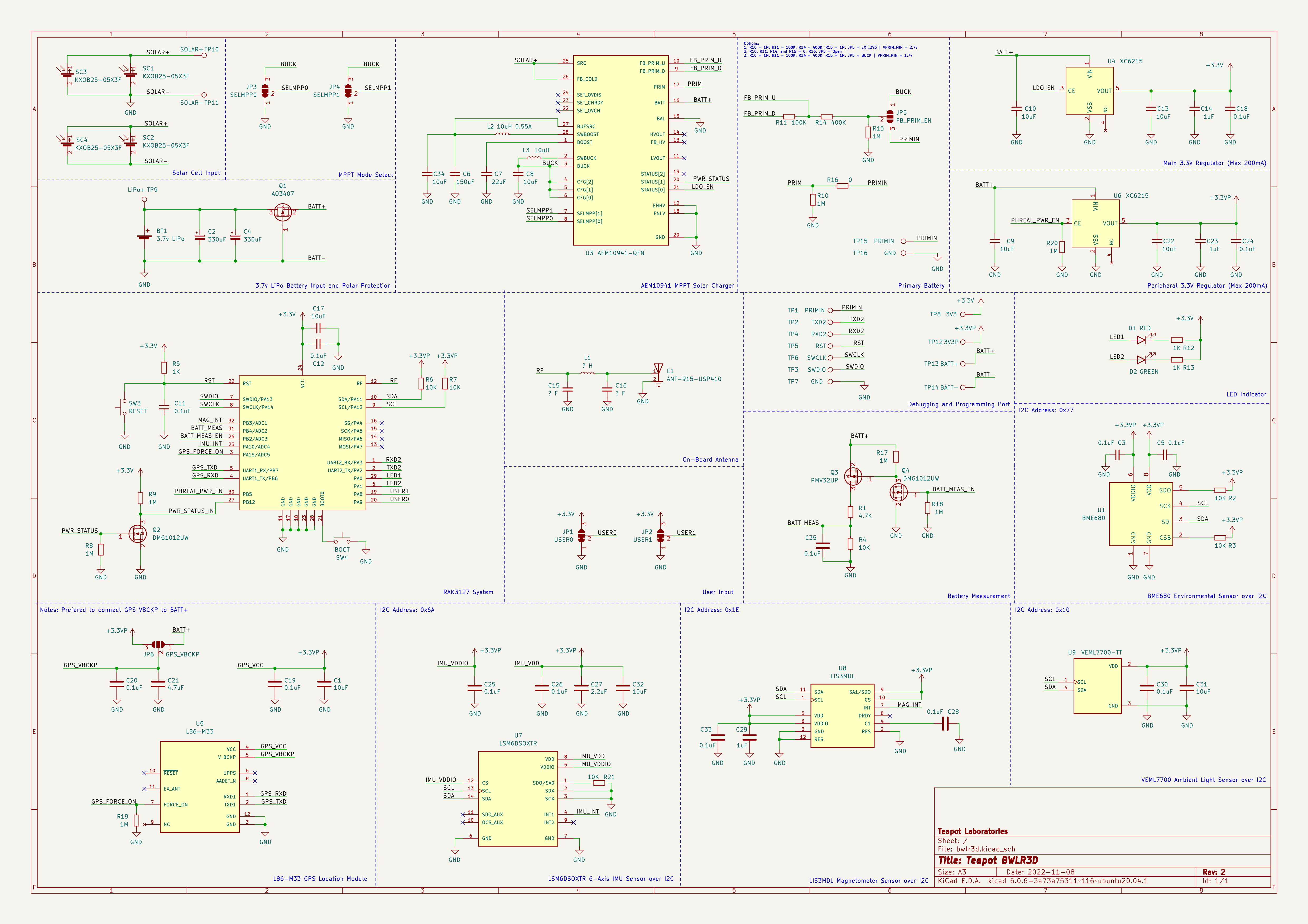
Schematic revisions:
- Revision 1: Initial design
- Revision 2: Swap BATT_MEAS and IMU_INT pin, and add 0.1uF to voltage divider

PCB Render
Built using KiCAD, the board is design to be as small as possible with all components placed on both side of the PCB. The following design are based on the latest revision.
| Top Board | Bottom Board |
|---|---|
|
|
|
|


PCB Top and Bottom Layout

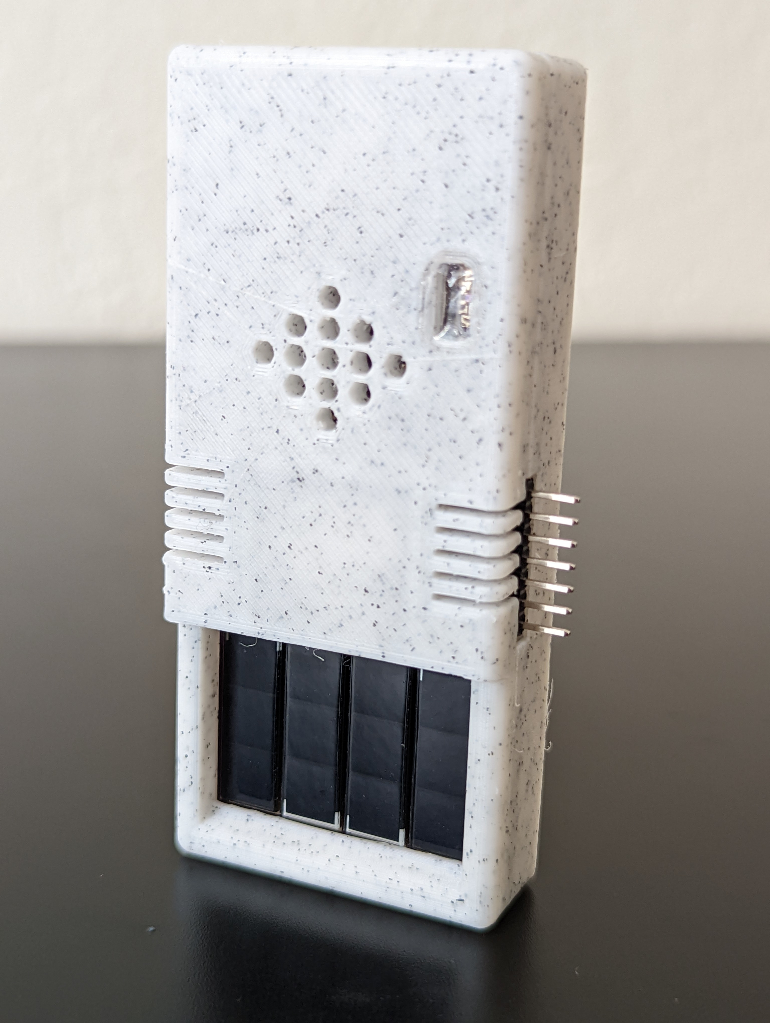
Built using TinkerCAD, the cases are available with 2 variant, with or without the programming port. The cases are 3D printable with any generic 3D printer with/without suppport (depends on the orientation). The STL files are available here

Case Open
The case is design to be as small as possible with an additional magnets in the back to ease the placement of the sensor. The following are the list of material used at the time of testing:
- 3.7v LiPo Battery, 500 mAh 50mm x 22mm x 48mm
- 4 piece of 8mm x 2mm neodymium magnet

Sensor Placement with Magnet
Power consumption and solar charging current are measured using Nordic PPK2 and CurrentRanger. The following are the summary of the measurement:
- Transmit 102 bytes @ 14dBm: 225ms @ 48mA
- Deep-Sleep : 12 uA
- GNSS Fix - Cold Start: 15s @ 38mA
- GNSS Fix - Hot Start: 5s @ 35mA
- Sensor Read: 1.36s @ 9mA
- Direct Sunlight Solar Charge: 12mA
- Indirect Sunlight Solar Charge: 454uA
Notes:
- GNSS time to fix depends on the conditions of the sky

LoRa Transmit

Deep-Sleep

GNSS Fix - Cold Start

GNSS Fix - Hot Start

Sensor Read
| Solar Charge - Direct Sunlight | Solar Charge - Indirect Sunlight |
|---|---|
|
|


More measurement can be found here
Most of the components are generic and can be bought from any electornics/semi-conductor distributor. RAK3172 is the only component available in RAKwireless store. The bill of materials can be downloaded here
⚠️ Be sure to buy the RAK3172 variant without IPEX to use the On-Board Antenna
| Id | Designator | Package | Quantity | Designation |
|---|---|---|---|---|
| 1 | BT1 | JST_PH_S2B-PH-K_1x02_P2.00mm_Horizontal | 1 | 3.7v |
| 2 | C14,C23,C29 | C_0603_1608Metric | 3 | 1uF |
| 3 | C17,C31,C32,C1,C9,C22,C8,C10,C34,C13 | C_0603_1608Metric | 12 | 10uF |
| 4 | C2,C4 | CP_EIA-3528-15_AVX-H_Pad1.50x2.35mm | 2 | 330uF |
| 5 | C21 | C_0603_1608Metric | 1 | 4.7uF |
| 6 | C27 | C_0603_1608Metric | 1 | 2.2uF |
| 7 | C5,C20,C26,C12,C28,C19,C30,C11,C25,C3,C33,C24,C18,C35 | C_0603_1608Metric | 14 | 0.1uF |
| 8 | C6 | C_1210_3225Metric | 1 | 150uF |
| 9 | C7 | C_0603_1608Metric | 1 | 22uF |
| 10 | D1 | LED_0603_1608Metric | 1 | RED |
| 11 | D2 | LED_0603_1608Metric | 1 | GREEN |
| 12 | E1 | ANT-915-USP410 | 1 | ANT-915-USP410 |
| 13 | L2 | IND_LPS4012-103MRB | 1 | 10uH |
| 14 | L3 | L_0603_1608Metric | 1 | 10uH |
| 15 | Q1 | SOT-23 | 1 | PJA3407 |
| 16 | Q2,Q4 | SOT-323_SC-70 | 2 | DMG1012UW |
| 17 | Q3 | SOT-23 | 1 | PMV27UPER |
| 18 | R1 | R_0603_1608Metric | 1 | 4.7K |
| 19 | R11 | R_0603_1608Metric | 1 | 100K |
| 20 | R12,R13,R5 | R_0603_1608Metric | 3 | 1K |
| 21 | R14 | R_0603_1608Metric | 1 | 400K |
| 22 | R16 | R_0603_1608Metric | 6 | 0 |
| 23 | R7,R2,R3,R6,R21,R4 | R_0603_1608Metric | 6 | 10K |
| 24 | R9,R8,R19,R15,R18,R10,R17,R20 | R_0603_1608Metric | 8 | 1M |
| 25 | SC4,SC1,SC3,SC2 | KXOB25-05X3F | 4 | KXOB25-05X3F |
| 26 | SW3 | SW_SPST_B3U-1000P | 1 | RESET |
| 27 | SW4 | SW_SPST_B3U-1000P | 1 | BOOT |
| 28 | U1 | BME688 | 1 | BME688 |
| 29 | U2 | RAK3172 | 1 | RAK3172 |
| 30 | U3 | QFN-28-1EP_5x5mm_P0.5mm_EP3.35x3.35mm | 1 | AEM10941-QFN |
| 31 | U5 | L86-M33 | 1 | L86-M33 |
| 32 | U6,U4 | SOT-23-5 | 2 | XC6215 |
| 33 | U7 | PQFN50P250X300X97-14N_0.59x0.30 | 1 | LSM6DSOXTR |
| 34 | U8 | LGA12_ST | 1 | LIS3MDL |
| 35 | U9 | VEML7700-TT | 1 | VEML7700-TT |
⚠️ Board can only be powered using the LiPo Battery
Programming the device can be done over the UART2 or SWD, available on the right side of the board. Out of the factory, the RAK3172 chip ships with an AT firmware that can be tested by connecting a USB-to-UART bridge to the UART2 port.
The following are some very good tutorial to start developing with the device:
- Communicating with the AT firmware
- Programming with Arduino
- Programming with STM32Cube
- Programming with MbedOS
For connecting to the UART2 port, use any USB-to-UART bridge module. In testing, the Sparkfun board is used for communication with AT firmware and programming over Arduino.
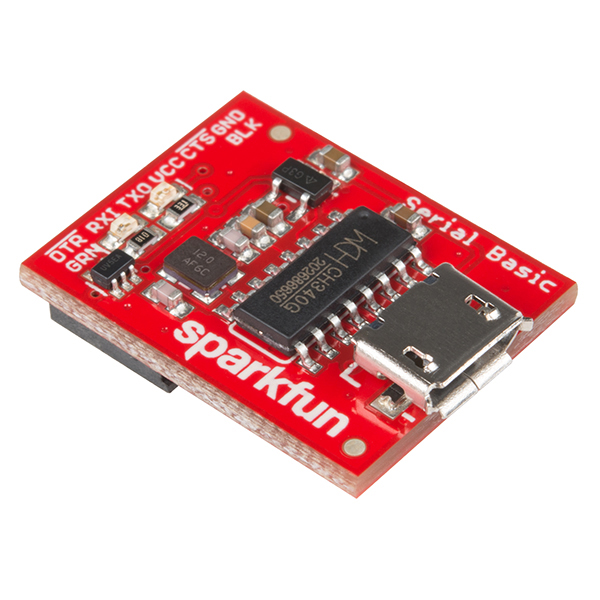
Sparkfun USB-to-UART Bridge
⚠️ Be sure to only use 3.3V module. Do not 5V module
For connecting to the SWD port, use ST-Link v2 in-circuit debugger and programmer from STM. In testing, ST-Link v2 clone will not work. The ST-Link v2 should atleast be reconizeable by the STM32CubeProgrammer. A cheap and alternative way to get an authorized ST-Link is to buy a Nucleo board, cut the top part which contain the ST-Link and use it as an external programmer.
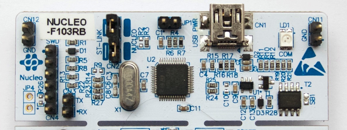
ST-Link v2 from a Nucleo Development Board
- https://www.radioshuttle.de/en/turtle-en/nucleo-st-link-interface-en/
- https://jeelabs.org/book/1547a/index.html
There are some issue, notes, and behavior that was discovered at the time of testing and development. The following are those discovery:
- Soldering the solar cell is better to be done manually using a soldering iron. Without proper reflow oven, it may damage the solar cell and reduces it's efficiency
- PRIMIN is available to use as the input for AEM10941 Primary Battery input. See schematic for more detail
The project won't be possible without the amazing work from people across the globe. The following are the reference to those awesome projects:
The product is open-source! However, some part of library used under src, might have it's own license. Please reach out or create a ticket to report any license violation.