I need an alarm for my garage.
You need to have:
- Risco ShockTec RK601SM0000B sismic sensor
- Raspberry Pi
The circuit is built using a Raspberry Pi as controller, and a Risco ShockTec RK601SM0000B as thief detection sensor.
Risco ShockTec RK601SM0000B is a NC (Normally Closed) sensor. If you give him a 3.3v tension so, you'll read 3.3v on the other side if is all ok, 0v if the sensor triggered (or the sensor is broken).
Risco ShockTec RK601SM0000B has 3 switches to determine why the alarm flag is raised:
- Tamper: There is a switch with a spring on the PCB inside the sensor. If someone tries to open it, it triggers. This triggers even if someone tries to use a magnet to "confuse" the sensor.
- Reed: A Reed sensor is placed on the PCB. This detects the presence of the magnet given with the sensor.
- Alarm: Triggers when the frequency of the vibrancy is inside the "thief" range (there is someone hammering on the window for example).
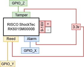
To wire this circuit you have to choose 3 free GPIO on your Raspberry Pi, and wire that as shown in the figure below. The sensor requires external power supply (in the manual is said between 9v and 16v, i used a 12v power supply), you need to wire it as shown in the figure below.
- GPIO_X: Is the pin to wire on Raspberry Pi for reading the Alarm Switch.
- GPIO_Y: Is the pin to wire on Raspberry Pi for reading the Reed Switch.
- GPIO_Z: Is the pin to wire on Raspberry Pi for reading the Tamper Switch.
This software system is based on a server which communicate with a Raspberry Pi placed in the alarmed zone.
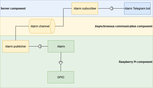
Below is described the architecture of the System. A server communicates asynchronously with the Raspberry (publisher/subscriber pattern). The Raspberry will produce a message if there's an alarm situation in the alarmed zone. All the components should be runnable on different nodes.
Elements short description:
- GPIO: Is just the software interface that Raspberry Pi offers to interact with GPIO ports on the board. GPIO ports on the board are connected to the Risco ShockTec RK601SM0000B sensor.
- Alarm: Reads data from GPIO (from the sensor), and triggers Alarm publisher if an alarm situation is detected.
- Alarm publisher: This element is a Proxy, it just pushes messages on the channel if requested to do that.
- Alarm channel: Publisher/Subscriber channel
- Alarm subscriber: This element is a Proxy, it just forward messages received on the channels where it is subscribed.
- Alarm Telegram bot: A Telegram bot. Forwards alarm messages, or warns if an alarmed zone doesn't reply to heartbeat.
This is a python implementation of the Telegram bot which should inform me when the alarm triggers.
Telegram uses a token based system to identify bot back-ends. You can see a guide about this here
To hide this token, i added a file called secrets to .gitignore. You just have to create a file called secrets, and paste your token inside it.
If you want to run this using Docker (recommended) open your terminal in telegram-bot directory of this project and:
- On Windows:
build-and-run.bat - On Unix:
sh build-and-run.sh
If you want to run this without docker, open your terminal in telegram-bot directory of this project and:
python telegram-bot.py