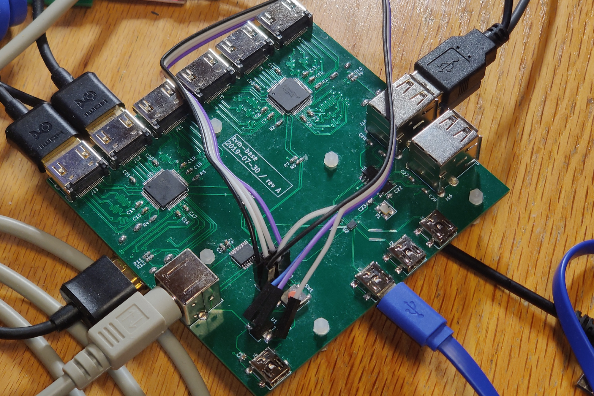
The main board for the open-source HDMI KVM switch I built. Contains HDMI and USB switch ICs, allowing you to share two monitors and four USB devices between three different computers.
This is a 1.6mm four layer PCB, designed for JLCPCB's JLC7628 impedance-controlled stackup. It most likely will not work (or will be limited in terms of HDMI performance) on another stackup.
It connects via a PS/2 cable to kvm-keypad—however, it does not use the actual PS/2 protocol.
Two TMDS361B chips are used as HDMI switches, and an FSUSB74 is used as the USB switch.
The full Bill of Materials is linked at the end of the README, and you should get the PCB fabricated at JLCPCB with their impedance-controlled JLC7628 process.
A stencil is probably the easiest way to assemble the board, but it's definitely possible to do so without one, as long as you have a hot air rework station. The trickiest parts to solder are probably the FSUSB74 (QFN with 0.4 mm pitch but no thermal pad) and the TMDS361B (TQFP with 0.5 mm pitch).
The HDMI connectors are also somewhat tricky, given that they are on both sides of the board and also have a relatively fine pitch. However, it's doable with a soldering iron, flux, solder wick, and ideally some form of magnification—you just have to be careful to ensure the pins are aligned with the footprint on the board before soldering.
Interestingly, the TMDS361B's datasheet pretty clearly states that it's "not intended for source side applications such as external switch boxes", which I probably missed when designing this board.
The consequences of this seem to be that there's little/no ESD protection on the sink side (the monitor output ports), and that the chip has a fairly weak sink-side output stage. That means you probably can't use the output with super long or super cheap cables. The inputs, however, should be fine, since TI claims that the TMDS361B has a "robust TMDS receive stage" that even works with out-of-spec HDMI signals.
Anecdotally, the output does seem to work, but I haven't tested it in that many conditions. This has been tested with a 3 foot HDMI cable going to an Acer EB243YU monitor, using a resolution of 2560 x 1440 at 75 Hz, which is outside of the TMDS361B's spec!
Theoretically, you might be able to work around this by running the output signals to another board with a retimer or redriver, but that's probably somewhat excessive. A future revision should use a different chip and/or integrate a retimer/redriver to the output stage. Unfortunately, it might be somewhat tricky to find an easily accessible HDMI switch chip—most seem to want you to sign an NDA before getting any documentation.
- TMDS361B's sink-side output stages, as mentioned above
- HDMI ports are too close together -- some cables might be too big to fit
- Some FSUSB74 ports seem to not be working -- this could be a soldering issue
- Port 2 works perfectly
- With ports 0 and 1, the computer detects a device but then complains the device is not responding
- Suspect that probably one of the D+/D- lines is not well connected
- The HPD and DDC lines are switched along with the ports. This means that switching ports will cause the connected source to think the monitor went away, which might not be what you want
- A future version will probably need to have some sort of EDID cloning/emulation, or have some way to keep the HPD line high after the monitor is connected?
- There is a workaround: cover the HPD pin (pin 19) of your HDMI cable with tape to block the HPD signal.
- This workaround means that some sources, like a laptop, might not autodetect your HDMI cable. You'll need to have some way to rescan. On Linux, you can try the command
xrandr --listmonitors. - This might be solvable by cutting the cable open and soldering a 10k resistor between HPD and +5V? That's somewhat extra though
- This workaround means that some sources, like a laptop, might not autodetect your HDMI cable. You'll need to have some way to rescan. On Linux, you can try the command
- The device can kinda sorta be powered by a sink—most likely the ESD diodes in the TMDS361B are backfeeding power on the +5V line.
- The keypad might have some trouble with noise when a PS/2 cable is connected, although it has been worked around in the firmware. A future revision might need a buffer or redriver or something similar? Plain I2C is probably not the best choice for communication between the base and keypad.