
CANFDuino is the best platform for open source CAN bus Arduino projects. It combines several essential features into one complete "ready-to-modify" package for the real world, including dual CANFD bus ports, SD card slot, and a multitude of analog/digital IO. It also includes a built-in prototyping shield for SMT and through-hole parts, and rugged packaging and connections.
For making connections the hookup guide is here: https://togglebit.net/canfduino-hookup-guide/
The following are steps for installing and testing CANFDuino support for the Arduino IDE (UPDATE tested 2.2.1), running and testing your first CAN sketch:
Note this content can also be found here https://togglebit.net/getting-started-with-canfduino/
Step 1. - Download the entie codebase, un-zip it. Rename "CANFDuino-master" to "CANFDuino".
Step 2. - Close the Arduino IDE if you have it open. Copy the whole "CANFDuino" folder to your local arduino hardware folder. The path for this hardware folder is: C:\Users\YOUR USERNAME\Documents\Arduino\hardware. The whole folder should be pasted directly into the hardware folder creating: C:\Users\YOUR USERNAME\Documents\Arduino\hardware\CANFDuino. If you do not have a hardware folder, create one and place CANFDuino folder inside of it.
Step 3. - Open the Arduino IDE, Go to the "Tools->Board->CANFDuino" to select the CANFDuino board as your target board. (If you have a CANFDuino based upon the SAMC21G17A processor, choose "CANFDuino17A" failing to do so may result in unsupported device message)
Step 4. - Go to Tools->Board->-Boards Manager-Wait for the downloads to finish. Click on “Arduino SAMD Boards (32-bits ARM Cortex-M3), including Arduino M0” and Install. This can take a while to download if you don't already have the library.
Step 5. - Go to File->Examples->CANFDuino->CANFDuino_Test500Kb.ino (have a look at all the other examples as well)
Step 6. - Wire the CANbus DB9 connectors or jump the 2pin headers on the PCB to connect CAN0 bus to the CAN1 bus. CAN0 High->CAN1 High, CAN0 Low->CAN1 Low.
Step 7. - Jumper at least one of the two termination resistors on the PCB enabling termnination resistors on the bus. (two ideally)
Step 8. - Connect USB cable to CANFDuino and the PC, this will power the unit an prompt for a dirver install. Wait for the driver to install if needed (one option is to skip obtaining from Windows and selecting the driver in the hardware\samd\drivers folder). Go to Tools->Port and select the COMM port that is labled CANFDuino. You may need to shut down the IDE and re-open it after installing the driver. (if needed, use FTDI exe in this repository to install driver, see link below for mac)
Step 9. - Go to Sketch->Upload. After compiling the IDE will send a signal to the CANFDuino to enter the bootloader. Note when the unit is bootloading the orange LED will stay on and strobe off quickly for 1-2 seconds. This occurs anytime the processor is reset (initial power on etc). You should see the green/red comms LED's flicker during sketch upload.
Step 10. - Go to Tools->Serial Monitor, note that this will also cause entry into bootloader for about 4-5 seconds before the sketch runs (for permanant code/bootloader bypass there is a jumper on the PCB).
Step 11. - See diagnostic printout in the comms window indicating pass/fail of testing. Typically the cause of failure is improper wiring or no termination resistor.
Ubuntu Flashing
-
download: https://www.mattairtech.com/software/arduino/Bossa-1.7.0-mattairtech-2-x86_64-linux-gnu.tar.gz
-
Extract and copy bossac and other binaries to installation path of bossac CANFDUINO Arduino Studio project path - cp -r * /home/disdi/Downloads/arduino-1.8.14/hardware/CANFDuino/tools/bossac/CANFDuinoBossac/
-
Flash the binary directly or via Arduno IDE sudo bossac --port=ttyUSB0 -e -w -v -b /tmp/CANFDuino_Test500kb.ino.CANFDuino.bin
Mac Flashing
-
Make sure the mac FTDI driver https://ftdichip.com/drivers/vcp-drivers/ is installed to recognize the device, the one included in this repo is for Windows.
-
Download the bossac programming utility https://github.com/shumatech/BOSSA/releases for mac and replace in the path C:\Users\PC\Documents\Arduino\hardware\CANFDuino\tools\bossac\CANFDuinoBossac.
All example sketches are found here. If you have followed the instructions above, all of the examples below are found locally on your machine in the C:\Users\YOUR USERNAME\Documents\Arduino\hardware\CANFDuino\samd\libraries\CANFDuino folder. This can also be accessed in the IDE by going to File->Examples->CANFDuino->.
CANFduino_SavvyCAN.ino

SavvyCAN is the awesome open source CAN bus tool developed by Collin Kidder. Programing the CANFDuino with this sketch will make it emulate an Arduino DUE board that is supported by SavvyCAN. This sketch has been tested for sniffing and transmission on both ports, with all settings getting saved into flash.
Steps for using SavvyCAN with CANFduino
Step 1. - Do everything above in getting started section to make sure yoru hardware works. Hook up the CAN/FD ports to the buss(es) you want to monitor.
Step 2. - Open ArduinoIDE, go to File->Examples->CANFDuino_SavvyCAN.ino
Step 3. - Upload it with the IDE and once complete place a jumper on "NO BOOT" pin to bypass the bootloader when the device is reset.
Step 4. - Download and install SavvyCAN for your platform. Watch Youtube videos on how to use SavvyCAN.
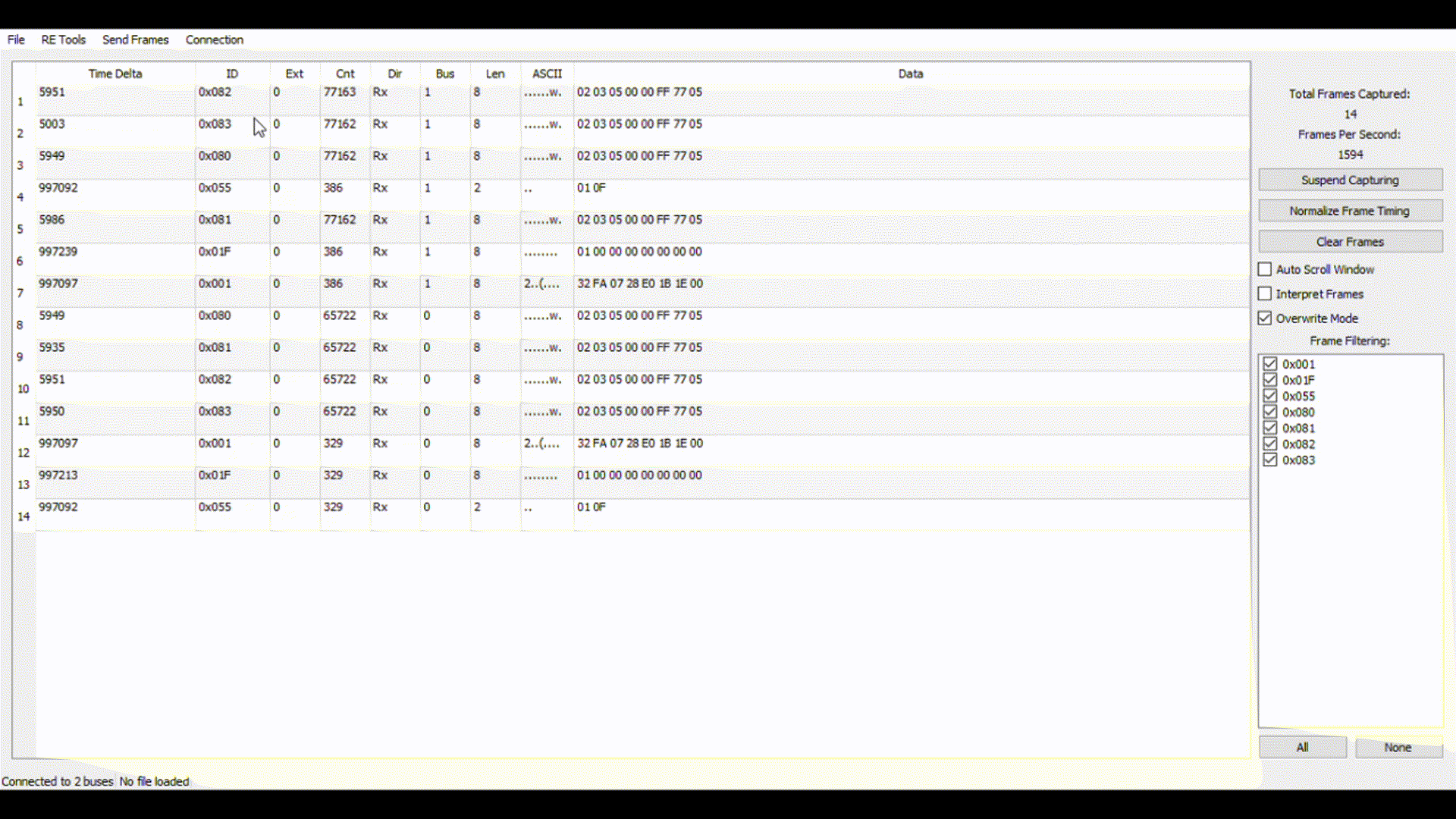
Step 5. - In SavvyCAN open the connection window, click "add new device connection" select "serial connection" you should see a COM port present corresponding to the CANFduino, click "create new connection".
Step 6. - From the connections settings window, select "enable console" to see the serial traffic including the heartbeat.
Step 7. - For CAN0 and CAN1 shown in the bottom tabs select "enable bus" and select the baud rate you wish to monitor from the drop down list.
Step 8. - Select "reset selected device" to reset the CANFDuino with the new baud rates. The baud rates will now be remembered and you do not need to reprogram the device each time you want to use SavvyCAN. If you are connected to a bus, you should see packets coming in the serial window, close this window to see the bus traffic in the main window.
Step 9. - If you have not connected to a bus, remember to set your termination jumpers on the CANFDuino, see the wiring guide here
When in doubt, power all other devices on the network down, open the connection window, make sure the bus is enabled, watch the serial console, and reset the device if needed (e.g. CAN bus goes into bus off state).
For a CANFD bus, use these steps
Step 1. - Do everything above in getting started section to make sure yoru hardware works. Hook up the CAN/FD ports to the buss(es) you want to monitor.
Step 2. - Open ArduinoIDE, go to File->Examples->CANFDuino_SavvyCANFD.ino
Step 3. - Upload it with the IDE and once complete place a jumper on "NO BOOT" pin to bypass the bootloader when the device is reset.
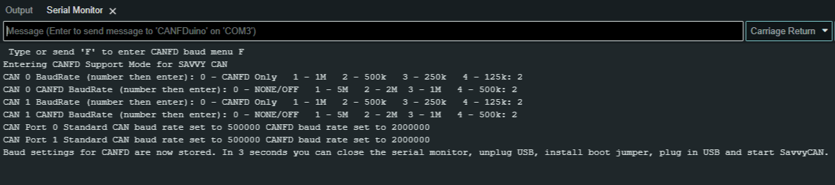
OPTIONAL: - We did build in a terminal interface for configuring the baud rates for CANFD and traditional CAN. If you want to pre-configure your unit before connecting to SavvyCAN, do NOT place the jumper on the NO BOOT pin and open up the serial monitor window in the ArduinoIDE with a 2MB serial port baud rate, and "carriage return" when pressing enter. Follow the on-screen prompts and type your responses (should only be a single number) followed by the return key until all of the baud rates are set. Now place the "NO BOOT" jumper on and power cycle (unplug USB, plug back in). See below, 2,2,2,2 results in both ports set for 500k/2MB CANFD. This does enable FD rates beyond 2MB.
Step 4. - Download our forked version of SavvyCAN from GitHub (Windows supported only right now). The entire codebase can be downloaded, with the windows executable located in the "release" folder. Additionally, you can watch Youtube videos on how to use SavvyCAN.
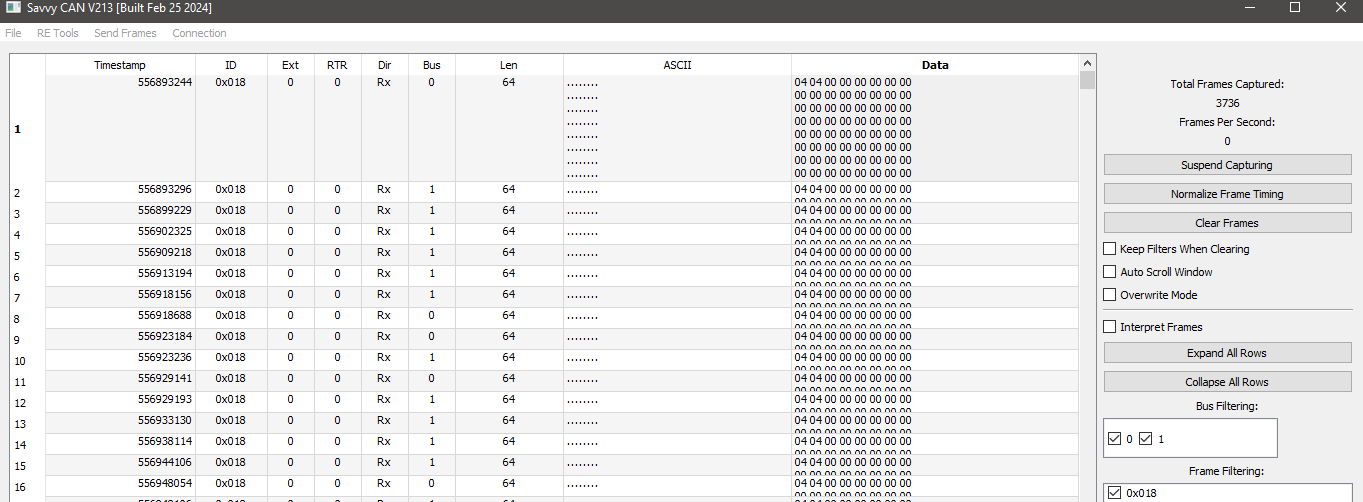
Step 5. -In SavvyCAN open the connection window, “Click Add New Device Connection”, select “enable console” to see the serial traffic including the heartbeat, click select “serial connection” and you should see a COM port present corresponding to the CANFduino, select “CAN-FD” checkbox then click “create new connection“. You should see messages confirming data tx/rx over the serial port in the console window. If you precofigured your baud rates and port settings in the Arduino IDE they will appear here. If there are no bau rate sttings, for CAN0 and CAN1 shown in the bottom tabs select “enable bus”, “enable CANFD” and select the standa”rd CAN “speed” and CANFD “baud rate” you wish to monitor from the drop down list. For each bus tab, click”save bus settings” (remember do this for both tabs after you set the bauds etc) then click on the GVRET device and check the status. It may say “connected” but if you may have no traffic in the console window click “reset selected device” to reset the CANFDuino with the new baud rates. The status will change from “not connected” to “connected” and traffic will reappear in the console window (clickclear to ensure there is traffic). The baud rates will now be remembered and you do not need to reprogram the device baud settings each time you want to use SavvyCAN. If you are connected to a bus, you should see packets coming in the serial window, close this window to see the bus traffic in the main window.
Step 6. -Ok now that we are connected time to connect to your CAN bus(s) and start sniffing. Remember you’ll want to understand where the terminations are and observe proper wiring in your network and if you need to enable one on your CANFDuino. You should now see traffic in the main window and the source of that traffic (CAN 0 or CAN 1). Note you will see longer messages on a CANFD bus of up to 64bytes! Really huge props to Collin Kidder for developing such a powerful tool for the community!
When in doubt, power all other devices on the network down, open the connection window, make sure the bus is enabled, watch the serial console, and reset the device if needed (e.g. CAN bus goes into bus off state). You can also reference this post with step by steps
CANFduino_CANTerm.ino
CANTerm is a cheapo 2 port CAN/CANFD packet monitor that can be used in simple serial terminal programs regardless of OS without special PC software. The CANFDuino is used to print packet payloads to the screen using terminal commands in static locations for easy viewing. Supports multiple CAN and CANFD baud rates, ID range filtering and stores the last settings into flash.
CANTerm has been tested with the PuTTY terminal program (2MBaud). PuTTY is probably the most flexible terminal tool for Windows, where the font size, number of lines, size of display can be configured to pack more data on one screen. https://www.chiark.greenend.org.uk/~sgtatham/putty/
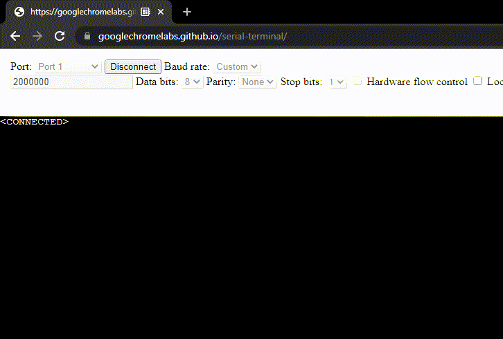
Monitor CAN bus traffic in the comfort of a Chrome browser with serial terminal from google's chromelabs (2MBaud). Just click the link below and connect to the COM port. https://googlechromelabs.github.io/serial-terminal/
Note: The Arduino Serial Monitor is not a terminal program and will not work.
10 Steps for using CANTerm
Step 1. - Do everything above in getting started section to make sure yoru hardware works. Hook up the CAN/FD ports to the buss(es) you want to monitor.
Step 2. - Open ArduinoIDE, go to File->Examples->CANFDuino_CANTerm.ino
Step 3. - Upload it with the IDE.
Step 4. - Open up your favorite terminal program (PuTTY, or click the chromelabs serial terminal link above), select the baud rate to 2MBaud, select the correct COM port and click connect. Wait for a few seconds for on-screen instructions to appear and follow them (if no on-screen instructions, check the baud rate and COM port setting and connect again).
Step 5. - Select if you want CAN0 or CAN1 or both ports to do packet monitoring.
Step 6. - Select the baud rate for CAN packets (or none)
Step 7. - Select the baud rate for CANFD packets (or none)
Step 8. - Type in the hex ID for the LOWEST ID you want to monitor (or type ALL for all packets to be monitored)
Step 9. - Type in the hex ID for the HIGHEST ID you want to monitor. All ID's between these ranges will pass through
Step 10. - If you selected 2 ports to monitor....you will be asked to repeat settings for the second port. Watch for traffic to hit the screen.
Note: if you do not want to wait the several seconds between power cycles or new terminal connections use the bootloader bypass jumper detailed in the hookup guide.
CANFDuino_GatewayCAN02CAN1.ino
This is a simple example of receiving a message on CAN0, modifying that message and re-sending it on CAN1. The example is very simple and looks for ID 0x100, modifies byte 0 and re-transmits on CAN1. The example uses a virtual function overload CallbackRx to implement the transmission when the message is detected as being received by RxMsgs which is simply a polling function that de-queues packets and can fireoff CallbackRx when a specific ID is detected. The user must define what happens in CallbackRx per the example below:
bool RxTx::CallbackRx(RX_QUEUE_FRAME *R)
{
  bool retVal = false;
    UINT8 i;
  if (R)
  {
    digitalWrite(3, HIGH);

    tx.id = R->rxMsgInfo.id;
    tx.len = R->rxMsgInfo.data_len;

    //copy all data bytes except byte 0
    for(i=1;i<tx.len;i++)
    {
      tx.data[i] - R->data[i];
    }
    //lastly modify byte 0, re-transmit on can port 1
    tx.data[0] = 0x80;
    CanPort1.TxMsg(&tx);
  }
  return(retVal);
}
CANFDuino_PassThruGateway.ino In this example, We will be intercepting the CAN lines from one "black box" to another with the CANFDuino int the middle acting as a "modifier-repeater". We are receiving a message on CAN ID 0x64 on CAN 0 modifying it's contents and re-transmitting it on CAN 1, and doing the same for message 0x200 on CAN 1 re-transmitting on CAN 0. We will also "pass-thru" all other messages bidirectionally between CAN 0 and CAN 1 as "untouched". The CAN bus should be physically broken (not spliced) with the upstream device wired to CAN H and CAN L signals on the CANFDuino shield port 0, and the downstream devices wired to CAN H and CAN L on CAN 1.
void loop()
{
         //note this code is just a polling example, not optimized for interrupt driven performance
         //poll for messages on ports
         CanPort0.RxMsgs();
         CanPort1.RxMsgs();

         //retransmit port 0 rx Messages on Port 1
         for (i=0;i<CanPort0.numRxMsgs;i++)
         {
             //intercept message 0x64 and modify byte 0 if it equals 55 before re-transmitting on port 1
             if(CanPort0.rxMsgs[i].rxMsgInfo.id == 0x64)
             {
                 if(CanPort0.rxMsgs[i].rxMsgInfo.data[0] == 0x55)
                 {
                    CanPort0.rxMsgs[i].rxMsgInfo.data[0] = 0x88;
                 }
             }
             //send all messages RX on CAN 0, and including moodified message
             CanPort1.TxMsg(&CanPort0.rxMsgs[i]);
         }

         //retransmit port 1 rx Messages on Port 0
         for (i=0;i<CanPort1.numRxMsgs;i++)
         {
             //intercept message 0x200 and modify byte 0 if it equals 55 before re-transmitting on port 1
             if(CanPort1.rxMsgs[i].rxMsgInfo.id == 0x200)
             {
                    CanPort1.rxMsgs[i].rxMsgInfo.data[0] = 0xFF;
             }

             //send all messages RX on CAN 1, and including moodified message
             CanPort0.TxMsg(&CanPort1.rxMsgs[i]);
         }
}
Note, as used in CANTerm, if alot of messages are expected, the following macro can be used to increase the reception buffer size #define MAX_NUM_RXFRAMES 64
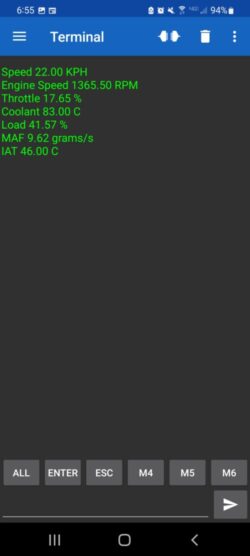
CANFDuino_OBD2Logger.ino
This is an example sketch that uses and OBD2 library to continously poll the OBD2 port of a vehicle and log the resulting data in CSV format to the SD card of the CANFDuino. The data is also printed to the serial monitor (LogScreen). This particular example polls for RPM, Speed, Throttle Position, Coolant Temp, Engine Load, Mass Airflow Rate, and Intake Air Temp. More data can be obtained by adding an cOBDParameter object for the item of interest, OBD2 is well documented a reference of parameters can be found here [https://en.wikipedia.org/wiki/OBD-II_PIDs] (https://en.wikipedia.org/wiki/OBD-II_PIDs). Have a look at the OBD2.h file and the parameters given in the example to get an idea how to properly add a new parameter (you will also need to modify the LogScreen, WriteOBD2header and logOBDData functions). Note that if you are using an OBD2 to DB9 cable, you need to watch the pinout of the DB9 as the CANFDuino uses 2,7 and 3 (see hookup guide), many OBD2 to DB9 cables use pins 3,5 and 1.
/***** DEFINITIONS FOR OBD MESSAGES ON CAN PORT 0, see https://en.wikipedia.org/wiki/OBD-II_PIDs to add your own ***************/
//char _name[10], char _units[10], OBD_PID pid,  uint8_t OBD_PID_SIZE size, bool _signed, OBD_MODE_REQ mode, float32 slope, float32 offset, cAcquireCAN *, extended ID;

cOBDParameter OBD_Speed(      "Speed "        , " KPH"    ,  SPEED       , _8BITS,   false,   CURRENT,  1,      0,  &CanPort0, false);
cOBDParameter OBD_EngineSpeed("Engine Speed " , " RPM"    ,  ENGINE_RPM  , _16BITS,  false,   CURRENT,  0.25,   0,  &CanPort0, false);
cOBDParameter OBD_Throttle(   "Throttle "     , " %"      ,  THROTTLE_POS, _8BITS,   false,   CURRENT,  0.3922, 0,  &CanPort0, false);
cOBDParameter OBD_Coolant(    "Coolant "      , " C"      ,  COOLANT_TEMP, _8BITS,   false ,  CURRENT,  1,    -40,  &CanPort0, false);
cOBDParameter OBD_EngineLoad( "Load "         , " %"      ,  ENGINE_LOAD , _8BITS,   false,   CURRENT,  0.3922, 0,  &CanPort0, false);
cOBDParameter OBD_MAF(        "MAF "          , " grams/s",  ENGINE_MAF  , _16BITS,  false,   CURRENT,  0.01,   0,  &CanPort0, false);
cOBDParameter OBD_IAT(        "IAT "          , " C"      ,  ENGINE_IAT  , _8BITS,   false ,  CURRENT,  1,    -40,  &CanPort0, false);
This is the same function as the OBD2 logger except we wire an RN-42 UART based bluetooth module in the prototyping area to Serial2. This enables a visual display of the OBD2 data on a paired Bluetooth device such as a phone or a tablet. In this case we use and Android phone and a "Serial Bluetooh Terminal" app developed by [http://www.kai-morich.de/android/} (Kai Morich) you can find in the google play store.
CANFDuino_Analog2CAN.ino
This example reads analog inputs A0 to A7 and sends the results over CAN bus in two messages 0x100 and 0x200. The values are sent most signficant byte first, and keep in mind the SAMC21 M0 is a 3.3V part, with a 12bit ADC. This means 0xFFF = 4096 = 3.3V by default (internal reference for ADC can be changed see Arduino library). The example code uses a simple periodic time poll to send them every xmSec and a DEBUG macro to optionaly print the values to screen. The packets could be stuffed a bit tighter but for simplicity we are sending 16bits for 12bit vavlues. Also, a single CANFD message could handle all of the analog inputs in one message.
CANFDuino_CAN2PWM.ino
This example reads the 8 byte contents of message 0x100 and drives 8 PWM outputs based upon these packet values. There are 16 pins that can bused as PWM output (see PWM output example code), in this exapmle we are using pins 18-26. The default PWM base frequency is about 700Hz.
CANFDuino_Test500kb.ino, CANFDuino_Test2Mb.ino
These are the sketches used in the getting started. With CAN0 and CAN1 wired together, they exchange messages to verify functionality and the outcome is printed to the serial monitor. The 500KBaud sketch uses standard CAN, the 2MB sketch uses CANFD.
CANFDuino_DigitalOut.ino, CANFDuino_DigitalPWM.ino, CANFDuino_DigitalInput.ino, CANFDuino_Analog.ino
These are all very simple test sketches for the basic Arduino analog inputs, digital inputs, and digital output functionality. All of the pins used in the sketches are labeled on the silkscreen.
CANFDuino_2WireMaster.ino, CANFDuino_2WireSlave.ino, CANFDuino_SerialTest.ino, CANFDuino_SPI.ino
These are the simple test functions for the serial interfaces that exist in the Arduino platform. Open the sketches to see the pinout or consult the "variant.cpp" file in the CANFDuino\samd\variants\ folder to see the mapping to the arduino IO.