Home
- Table of Contents
- Hardware Overview
- A closer look at the T1902 and T1942 head units
- Serial Communication between head unit and Fortius brakes
- Communication protocols of cable based trainers
- Protocol of older wireless ANT Tacx trainers
- Protocol of Smart Tacx trainers with wireless ANT FE-C
***This is a collection of information from the internet, together with own investigations. Not every information is confirmed. Please report if you find any wrong information. ***
*** WORK IN PROGRESS ***
There are two major kind of brakes: magnetic (eddy current) brakes and motor brakes.
To control magnetic brakes, there are two ways: manually with a bowden control cable or electrically. The motor brakes are always controlled electrically.
A (manual) magnetic brake is controlled by a bowden cable, which changes the distance of magnets to a rotating plate.
For electrical brakes, some kind of device controls the motor force or an (electrical) magnetic field.
The unit can be a stand-alone unit or a (host) computer controlled unit. Sometimes the controller is inside the brake and sometimes the controller is an external head unit connected to the brake by wire or wireless. The cable is always a full connected 6P6C RJ12 (RJ-25) cable. The wireless technology of the Tacx brakes are always ANT+. There are two different ANT+ protocols. Older brakes talk a proprietary protocol. The newer brakes talk a portable ANT+ FE-C protocol (fitness equipment control).
"Wheel On" magnetic brakes are
- Basic, Excel and Grand Excel (sometimes called Cycleforce ...)
- i-Magic
- Flow
- Vortex
- Satori (non electrical, but with wireless feedback)
"Wheel On" motor brakes are
- Fortius
- Cosmos
- Bushido
- Genius
"Direct Drive" magnetic (electrical) brakes are
- Flux (S), Flux 2
"Direct Drive" motor brakes are
- Neo, Neo 2
Tacx calls some of their trainers "smart". Smart means, that these trainers support the newer (standardized) ANT+ FE-C protocol together with Bluetooth 4.0.
Other name additions are VR, Multiplayer (typically bundled with TTS software, a steering device and a multiplayer license).
Note: There is a so called "PC Smart Upgrade (T2990)". This is a bundle with TTS4 (advanced), a wireless "control device" (T2022, with a built-in receiver for legacy heart belts) and an USB ANT+ antenna (T2028). The "control device" talks the old proprietary ANT+ protocol.
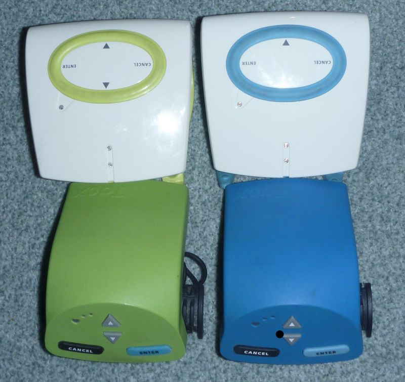
- T1904 green-ring head unit (Upper left)
- T1932 blue-ring (Upper right)
- T1902 solid-green (Lower left)
- T1942 solid-blue (Lower right)
WIP
| Abbreviation | Description |
|---|---|
| M | motor brake |
| E | eddy current (magnetic) |
| EU | 50 Hz / 230 V (Europe) |
| US | 60 Hz / 110 V (US) |
| HU | head unit |
| RJ12 | RJ12 cable |
| CAD | socket for Cadence |
| ANT | legacy ANT+ |
| ANTFEC | ANT FE-C controlled |
| Acc | Accessory |
First some notes about 32 and 64 bit compatibility of some of the PC products: The (non wireless) PC head units are plain vanilla USB (1.1) and they work with 32 bit and 64 bit. The problem with the older head units is, that TACX do not support a firmware loader for the older firmware and the newer TTS software does not support the older communication protocol of the T1902 firmware.
| Tacx № |
Product | Type | Year | Description | Additional Information |
|---|---|---|---|---|---|
| T1601 | Cycleforce Excel/Basic brake | E, EU | 199x | electro-magnetic brake, RJ12, CAD | similar, but not identical to Flow brake i.e. PC-head unit T1904 and T1932 can not drive legacy T1601 |
| T1620 | Cycleforce Excel bundle | E, EU | 1995 ? | T1601 brake, T1642 head unit | |
| T1640 | Cycleforce Grand Excel bundle | E, EU | 1995 ? | T1601 brake, T1642 head unit | also contains a so called 'grand excel USB interface' ? |
| T1642 | Cycleforce Excel stand-alone unit | E, EU | 1995 ? | stand-alone head unit | has parallel port to connect PC or Printer |
| T1652 | Cycleforce Basic stand-alone unit | E, EU | 1995 ? | stand-alone head unit | |
| T1670 | Cycleforce Basic bundle | E, EU | 1995 ? | T1601 brake, T1652 head unit | |
| T1680 | Flow bundle | E, EU | T1901 brake, T1682 head unit, T1690 skyliner | ||
| T1682 | Flow stand-alone unit (orange) | E, EU/US | stand-alone head unit | ||
| T1684 | Flow bundle | E, US | T1911 brake (US), T1682 head unit, T1690 skyliner | ||
| T1690 | front wheel skyliner | Acc | |||
| Tacx № |
Product | Type | Year | Description | Additional Information |
| T1900 | i-Magic bundle | E, EU | T1901 brake, T1902 PC-head unit, TTS3 software | ||
| T1901 | Flow, i-Magic brake | E, EU | new electro-magnetic brake, RJ12, CAD | controllable with T1902, T1904, T932 (1942 head unit with special firmware) | |
| T1902 | i-Magic solid green PC-head unit | E/(M), EU/US | ? | USB PC-head unit, RJ12 and steering connector | Needs firmware after every power up. Compatible to brakes T1601, T1901, T1911 (T1941, T1946 motor brakes with special firmware) |
| T1904 | green ring PC-head unit | E/M, EU/US | ? | USB PC-head unit, RJ12 and steering connector | built-in firmware. Can drive brakes T1901, T1911, T1941, T1946. NOT compatible with T1601 brake |
| T1905 | steering frame | Acc | Mini-DIN, Connects to for T1901, T1904, T1935, T1942 head units | potentiometer inside - like old game-port analog joystick | |
| T1911 | Flow, i-Magic brake (US) | E, US | for 110V power | controllable with T1902, T1904, T932 (1942 head unit with special firmware) | |
| T1912 | Flow, i-Magic bundle (US) | E, US | T1911 brake, T1902 head unit, TTS3 software | ||
| T1915 | i-Magic upgrade Kit | E/(M), EU/US | T1902 head unit, simple Software | no TTS software?? | |
| T1925 | Fortius upgrade kit | E/M, EU/US | T1932 Blue Ring PC-head unit, Software | TTS4 Basic?? | |
| T1930 | Fortius Multiplayer bundle | M, EU | T1941 brake, T1932 PC-head unit, T1905 steering, Software | ||
| T1932 | blue ring PC-head unit | E/M, EU/US | USB PC-head unit, RJ12 and steering connector | built-in firmware. Can drive brakes T1901, T1911, T1941, T1946. NOT compatible with T1601 brake | |
| T1935 | Fortius Multiplayer bundle | M, US | T1946 brake, T1932 head unit, T1905 steering, Software | ||
| T1940 | Fortius bundle | M, EU | T1941 brake, T1932 head unit | no steering frame, no one year multiplayer license | |
| T1941 | Fortius brake | M, EU | motor brake, powerback with RJ12, CAD | 19200, 8N1 3.3V TTL communication | |
| T1949.50 | Fortius power unit | M, EU | just the powerback for T1941 | ||
| T1942 | Fortius solid blue PC-head unit | (E)/M, EU/US | USB PC-head unit, RJ12 and steering connector | Needs firmware after every power up. For motor brakes T1941, T1946. (T1601, T1901, T1911 with special firmware) | |
| T1945 | Fortius bundle (US) | M, US | T1946 brake, T1932 head unit | no steering frame, no one year multiplayer license | |
| T1946 | Fortius brake (US) | M, US | motor brake, powerback with RJ12, CAD | 19200, 8N1 3.3V TTL communication | |
| T1949.50 | Fortius power unit | M, US | just the powerback for T1946 | ||
| Tacx № |
Product | Type | Year | Description | Additional Information |
| T1960 | Vortex bundle | E, EU | 2008 | T1961 brake, (legacy) head unit | Tacx PDF |
| T1961 | Vortex brake | E, EU | wireless legacy-ANT+ controlled 230V 50/(60) Hz magnetic brake | 8 Neo magnets, 8 electro-magnets, max power 950W (60 kph) | |
| T1970 | Cosmos bundle | M, EU | ? | T1941 motor brake, T1972 stand-alone head unit | upgradable with every PC-head unit for T1941/T1946 brakes |
| T1975 | Cosmos bundle (US) | M, US | T1946 motor brake (US), T1972 stand-alone head unit | upgradable with every PC-head unit for T1941/T1946 brakes | |
| T1972 | Cosmos Computer standa-alone unit | stand-alone head unit for motor brakes, RJ12 | |||
| T1980 | Bushido bundle | M | 2008 | T1981 brake, T1982 stand-alone head unit |
No main power required, legacy-ANT+ PDF 1, PDF 2 |
| T1981 | Bushido brake | M | wireless legacy-ANT+ controlled motor brake |
No main power required , controllable via ANT+ (PC/TTS4, Tacx Cycling App, T1982 stand-alone unit) |
|
| T1982 | Bushido Computer stand-alone unit | Dark Grey stand-alone head unit, legacy-ANT+ | TTS4 PC-software can talk to T1982, T1982 can talk to T1981 | ||
| Tacx № |
Product | Type | Year | Description | Additional Information |
| T2000 | i-Genius Multiplayer bundle | M | 2012 | Brake, T2022 head unit, T2028 antenna, TTS4 software, T2420 steering, multiplayer license | |
| T2010 | i-Genius Multiplayer Smart bundle | M | probably later rebranded to Genius Smart (T2080), | ||
| T2020 | i-Genius bundle | M | Brake, T2022 head unit, T2028 antenna, TTS4 software | ||
| T2022 | Genius remote | Acc | legacy-ANT+ Controller 'blue ufo' handle bar with 5KHz EM heart-belt receiver | can control Bushido, Genius, Ironman | |
| T2028 | ANT+ Antenna | Acc | USB ANT+ receiver with antenna and a long USB cable | ||
| T2050 | Ironman bundle | M | Rebranded T2020 i-Genius ? | ||
| T2060 | Ironman Smart bundle | M | Rebranded T2080FC plus World Championship Kona DVD ? | ||
| T2080 | Genius Smart bundle | M | 2015 | ANT+ FE-C and Bluetooth, controlled via App | new portable ANT+ FE-C (fitness equipment control) |
| T2080FC | Genius Smart Full Connect bundle | M | ANT+ FE-C and Bluetooth, T2022 head unit, T2028 antenna, TTS4 software, | ||
| Notes | |||||
| Tacx № |
Product | Type | Year | Description | Additional Information |
| TODO | |||||
| T2162 | (green) i-vortex head unit? | green sides, ANT+ wireless | |||
| T2170 | i-Vortex | ||||
| T2171 | i-Vortex resistance unit 110/230 Volt | ||||
| T2172 | i-Vortex head unit | white/gray with blue sides, ANT+ wireless | |||
| T2179 | Skyliner | , vortex, i-vortex, Flow ... | |||
| T2180 | Vortex Smart | ||||
| T2181 | Vortex Smart resistance unit | ||||
| T2180FC | Vortex Smart Full connect | ||||
| Tacx № |
Cat | Type | Year | Description | Additional Information |
| TODO | |||||
| T2200 | Flow | E, EU | 2011 | ||
| T2210 | Flow (US) | E, US | |||
| T2220 | Flow Multiplayer | E, EU | 2011 | ||
| T2230 | Flow Multiplayer (US) | E, US | 2011 | ||
| T2240 | Flow Smart | E | 2015 | ANT+ FE-C and Bluetooth, controlled via App | |
| T2240FC | Flow Smart Full connect | E | 2017 | ANT+ FE-C and Bluetooth plus T2022, T2028, TTS4 software | |
| T2250 | i-Flow | E, EU | 2012 | ||
| T2250 | i-Flow | E, US | 2012 | ||
| Tacx № |
Cat | Type | Year | Description | Additional Information |
| T2420 | Blacktrack steering | Acc | wireless legacy-ANT+ steering frame | mountable with ... |
| Product | Power (W) (@ km/h) | Incline (%) | Torque (Nm) | Brake Force (N) | Flywheel | Flywheel inertia (kg * m^2) | Calibration | Simu. of descent |
|---|---|---|---|---|---|---|---|---|
| Basic T1601 | 600 W | 5% | ~2kg ? | Spin Down | No | |||
| Flow T1901/T1911 |
800 W | 1.65 | ||||||
| Fortius, Cosmos T1941/T1946 |
1000 W | virtual | test run | yes | ||||
| Genius T2021 | 1500 W | 20% | virtual | yes | ||||
| Vortex T1961 | 950 W | 1.65 kg | ||||||
| Bushido T1981 | 1400 W | 1.65 kg | ||||||
| Flow (smart) T2240 | 800 W (40) | 6% | 15.3 | 45 | 1,6 kg | 11.8 kg | Spin down | No Source |
| Bushido smart T2780 | 1400 W (40) | 15% | 44 | 128 | virtual & 1,2 kg | mass & virtual (60kg) | Spin down | No Source |
| Vortex smart T2180 | 950 W (40) | 7% | 16.3 | 48 | 1.65 kg | 11.8 kg | Spin Down | No Source |
| Satori smart T2400 | 950 W (40) | n/a | 16.3 | 48 | 1,6 kg | 16.9 kg | Spin down | No Source |
| Genius Smart T2081 | 2000 W (40) | 20% | 51 | 150 | virtual | virtual (125kg) | Auto | Yes Source |
| Flux, T2900 | 1500 W (40) | 10% | 22.1 | 65 | 7 kg | 22.8 kg | Spin down | No Source |
| Flux S, T2900S | 1500 W (40) | 10% | 22.1 | 65 | 7 kg | 22.8 kg | Spin down | No Source |
| Flux 2, T2980 | 2000 W (40) | 16% | 41 | 120 | 7.6 kg | 31.2 kg | Spin down | No Source |
| Neo | 2200 W (40) | 25% | 85 | 250 | virtual | virtual (125 kg) | not required | Yes Source |
| Neo 2 | 2200 W (40) | 25% | 85 | 250 | virtual | virtual (125 kg) | not required | Yes Source |
The head units do not have a non volatile memory except the EEPROM, which contains the initial USB descriptor and the individual device ID. So, the firmware has to be loaded after every power up (under linux i.e. with the fxload tool).
Tacx always says, that the solid-green will work only on 32bit systems. To clarify this:
It is NOT(!) a problem with 32bit or 64bit systems.
You can easily load the firmware with the "fxload" tools under every operating system. There is a little python script, that can do the thing without any native binaries.
You can find the original firmware on most of the Tacx DVD inside the driver directory. The T1942 firmware file is named FortiusSWPID1942Renum.hex. The original T1902 firmware is part of a the I-magic.sys file. You can cut it out of the File with a little helper tool (LINK).
The steering frame connects via a Mini-DIN socket to the T1902, T1904, T1932, T1942 head units. Only two wires are used. Inside the steering they connect to a 100 k-ohm potentiometer. T1902 and T1942 head units measure the resistance the game-port style (See wikipedia). There is a NE585 (4x NE555) timer inside.
The eddy-current (magnetic) brakes have 6 permanent magnets (newer brakes have 8 magnets) and the same number of (head unit controlled) electro-magnets. With the electro-magnets switched off, the only magnetic force comes from the permanent magnets.
What happens if the electro magnets are switched on, depends on the timing of the switching. The source of the magnetic field is your power line sinus voltage. On one half of the sinus period, the electro magnetic field reduces (compensates) the field of the permanent magnets and in the other half of the period the electro magnetic field increases the permanent magnetic field.
The head unit switches the electro magnets on and off, synchronized to the power line phase to increase or decrease the permanent magnetic field. The length of the pulse depends on the selected resistance.
It's is a little like a RPC (reverse phase control) device synced with your power line frequency. NOTE: Literature recommends "phase angle control" for inductive loads, but as far as I understood the brake control, TACX uses RPC. TODO: Have to verify this!
The CPU in the "solid" head units are an EZ-USB an2131s from Cypress that is fairly flexible (see AN2131).
; T1902 (solid green)
; T1942 (solid blue)
;
; EZ-USB port:
;
; ===========================================================================
; PORT A (same for Imagic & Fortius)
; ===========================================================================
;
; OUTA PINA.4 0x10 LED Red
; OUTA PINA.5 0x20 LED Green
;
; ===========================================================================
; PORT B (same for Imagic & Fortius)
; ===========================================================================
;
; similar to imagic: BIT 4-7 Buttons (IN), BIT 0-3 "Gameport"  OUT/IN
; PINB/OUTB 0x0f : 555/585 Timer for Gameport/Steering (steering is Bit #2 = mask 0x04)
; PINB 0xf0 : Buttons (enter: 0x10, down: 0x20, up: 0x40, cancel: 0x80)
;
; ===========================================================================
; PORT C
; ===========================================================================
;
; PINSC.7 magnetic field switch (or :Tx) (only "solid green" T1902) - 1:on 0:off
; PINSC.6 not connected / unknown
; PINSC.5 Heartbeat                 (alt function: connected to 'T0')
; PINSC.4 Cadence (on T1901)        (alt function: connected to 'T1')
; PINSC.3 power line "zero crossing" (alt function: connected to INT1)
; PINSC.2 Wheel (or: Rx)            (alt function: connected to INT0) (see note 1)
; PINSC.1 connected to Tx0 (only on "solid blue" T1942)
; PINSC.0 connected to Rx0 (only on "solid blue" T1942) (see note 1)
;
; Note 1: on the "solid blue" head unit the "blue" wire is connected to the PINSC.2 and PINSC.0!
;
| Pin# Port C | dir | Dev | function | |
|---|---|---|---|---|
| C.0 | IN | Serial0 | B | Rx Alt-Function (OUT) - for T1941 motor brake communication |
| C.1 | OUT | Serial0 | B | Tx Alt-Function - for T1941 motor brake communication Can be "misused" as magnetic field PAC/PWM/RPC when used with T1601/T1901 eddy current brake |
| C.2 | IN | INT0 | B/G | Wheel-Sensor (only when powered) for T1901-EddyCurrent-Brake (T1902: Rx) |
| C.3 | IN | INT1 | B/G | Power-Line-Frequency zero crossing (only when T1601/T1901 is powered) |
| C.4 | IN | T0 | B/G | CAD on T1901 brake, works also with unpowered T1601/T1901 (detected by sampling) |
| C.5 | IN | T1 | B/G | HR - works without brake connected (detected by sampling) |
| C.6 | (IN) | unused? | ||
| C.7 | OUT | G | "PAC/PWM/RPC-controls" magnetic field of T1601/T1901 eddy current brake. Can be "misused" as TX when used with T1941 motor brake |
( "B" is "blue" device, "G" is "green" device )
; =======================================
; head unit backside socket
; =======================================
;
;      __|^^^|__
;    _|         |_
;    |           |  cable  |  connect to AN2131 PINC# (H/L: signal default when port is 'IN')
;    |           |  wire   |       solid-blue         solid-green
;    |6 5 4 3 2 1|  ------------------------------------------------
;     | | | | | |__ white  |          4  (H)            4  (H)  (3.3V TTL - used as TTL IN for CAD)
;     | | | | |____ black  |         --- (L)           --- (L)  (GND, mass?)
;     | | | |______ red    |          1  (L)            7  (L)  (3.3V TTL - used as TTL OUT for PWM,Serial-TX)
;     | | |________ green  |          3  (L)            3  (L)  (sinus (AC) ~15V internally converted to 0V/~5V)
;     | |__________ yellow |         ---               --- (Voltage/Power from brake 15-18V (T1601) or 5.8V (T1942))
;     |____________ blue   |     0 and 2 (H)            2  (H)  (3.3v TTL? - used as TTL IN for Wheel, Serial-RX)
;
; Yellow wire: I haven measured the voltage under load. Probably you can power a stand alone head unit with
;              it - it is not used if you have a host-powered head unit
;
; One can see, that on both devices the important wires are connected to a pin
; at the CPU. Unfortunately the serial communication function of the motor brake
; is not connected to the serial0-Tx/Rx pins in the 'solid-green' head units.
; The only way to control the motor brake with the solid-green is to emulate
; a serial signal by decoding the raw signal on PINC.2 (INT0) for Rx and
; by "bitbanging" the data on PINC.7 for Tx, which is time critical and more
; expensive - but possible.
;
; =======================================
; Brake backside socket
; =======================================
;
;      __|^^^|__
;    _|         |_  original|
;    |           |  cable   | T1941: motor brake                (T1901 eddy current brake)
;    |           |  color   |
;    |6 5 4 3 2 1|  ----------------------------------------------------------------------------
;     | | | | | |__ white   | T1941: not used                   (T1901: CAD sensor - TTL OUT)
;     | | | | |____ black   | T1941  GND                        (T1901: also GND)
;     | | | |______ red     | T1941: Brake-Rx, Host-Tx (3.3V !) (T1901: magnetic field 'PWM' switch - TTL IN)
;     | | |________ green   | T1941: not used                   (T1901: power line sinus +/- 20V - analog OUT)
;     | |__________ yellow  | T1941: ~6V                        (T1901: >12V analog OUT ) (maybe to power stand-alone head units? )
;     |____________ blue    | T1941: Brake-Tx, Host-Rx (3.3v !) (T1901: wheel signal, TTL OUT)
;
The TACX USB vendor ID is 0x3561.
The blue-ring head unit has ID "3561:1932" and the green-ring has "3561:1904". I own a blue-ring and green-ring head unit and a both are all-in-one units, that can handle both brakes (the eddy-current-brake T1902 and the motor brake T1940) Note: the newer 'blue ring' and 'green ring' head units can not driver the old T1601 eddy current brake sold with the Basic, Excel and Grand Excel.
| Device | USB Id | Notes |
|---|---|---|
| T1902 | 3561:1902 | Old "solid green" IMagic head unit (with or without loaded firmware) |
| T1904 | 3561:1904 | New "white green" IMagic head unit (white body with green or (sometimes) white ring - firmware inside) |
| T1932 | 3561:1932 | New "white blue" VR head unit (white body with blue ring - firmware inside |
| T1942 V1 | 3561:e6be | Old "solid blue" Fortius head unit (without firmware loaded) |
| T1942 V2 | 3561:1942 | Old "solid blue" Fortius head unit (with firmware loaded) |
You can load the firmware of the "solid blue" device (FortiusSWPID1942Renum.hex) also to the solid green/yellow/white. The solid green head unit 'magically' converts to a 'solid blue' one. This works at least on the devices I own.
BUT: You have to control the brake different, because the PCB layout between the CPU (PortC) and the serial cable is a little different. The green unit uses PINC.7 to controlled the magnetic field, whereas the blue unit uses the serial interface on PINC.0 / PINC.1.
ATTENTION: maybe the power line signal from the magnetic brake has 16v voltage level (no 3.3TTL). Maybe the blue head unit cannot handle this (but mine is still alive). I have not checked the wiring on the PCB.
On linux:
fxload -I FortiusSWPID1942Renum.hex -d /dev/bus/usb/xyz/abc
where "xyz" is the bus number and "abc" is the device number
For example try the following:
$> lsusb -d 3561:
Bus 002 Device 011: ID 3561:1902
$> fxload -I FortiusSWPID1942Renum.hex -d /dev/bus/usb/002/011
$> lsusb -d 3561:
Bus 002 Device 012: ID 3561:1942
In this example, the device now has a new ID 012 on bus 002 and a new unit ID "3561:1942" That's the ID of the "solid blue". 3561 is the ID of "Tacx bv".
Funny - isn't it.
The device can send up to 6 bytes. Less bytes are allowed.
| Byte № |
Description | Notes |
|---|---|---|
| 0 | desired 'force' value. | Range is 0x00...0xFF 0x80 is 'neutral' (electrical magnetic field switched off). Values less than 0x80 reduce brake force (electrical magnetic field reduces the static magnetic fields) and values greater than 0x80 increase the brake force (electrical magnetic field increase the static magnetic fields). |
| 1 | start/stop control | Only Bits 0-2 are used: * 0x01 PAUSE/START manual control of stop watch * 0x02 AUTOPAUSE - if wheel is less than '20' * 0x04 AUTOSTART if wheel is greater or equal 20 To force a start without wheeling you need to start the stopwatch (Bit0=1) and disable auto-stopping (Bit1=0). Bit2 does not matter. Auto-Start/Stop is achieved with 0x06 |
| 2 | Set stop watch high byte | optional |
| 3 | Set stop watch mid byte | optional |
| 4 | Set stop watch low byte | optional |
| 5 | Set stop watch hundreds | optional, different for older firmware versions |
| Byte № |
Description | Notes |
|---|---|---|
| 0 | Status and Cursors | Bit0: 0x01=HeartBeat Bit1: 0x02=Power-Detect Bit2+3: power line frequency * 0x0C: 50Hz * 0x08: 60Hz * 0x04: unused * 0x00: <50Hz Bit4: 0x10=Enter Button Bit5: 0x20=Down Button Bit6: 0x40=Cancel Button Bit7: 0x80=Up Button |
| 1 | WheelSpeed High | turns of the wheel in the last second? |
| 2 | WheelSpeed Low | |
| 3 | Cadence | RPM revolutions per minute) |
| 4 | HeartRate | BPM (beats per minute) |
| 5 | Stopwatch Seconds High | |
| 6 | Stopwatch Seconds Mid | |
| 7 | Stopwatch Seconds Low | |
| 8 | Stopwatch Hundreds | |
| 9 | Resistance value of brake | |
| 10 | PedalSensor | Bit 5: 0x00 or 0x10 |
| 11 | Axis 1 | floating between 0xBf-0xC3 |
| 12 | Axis 2 | 0x00-0xff Steering if plugged https://en.wikipedia.org/wiki/Game_port |
| 13 | Axis 3 | Unused? always 0x00 |
| 14 | Axis 4 | Unused? always 0x00 |
| 15 | Counter | running 0-255 every 70-80 ms, (old firmware fa, 1a) |
| 16 | Wheel Count | Number of Counts of (metal) wheel since last call (~70-80ms)? |
| 17 | Year | YY: individual Year of production of YOUR unit (20YY) |
| 18 | Serial High | YOUR individual Device-ID (high) |
| 19 | Serial Low | YOUR individual Device-ID (low) |
| 20 | Firmware-Version | 0x1c new, 0x1a old |
Bytes 17-19: matches YOUR sticker on head unit backside
// Legacy:
struct frameCommandImagic {
    // brake load/resistance
    uint8_t  load;

    //  Stopwatch Control (0x01/0x04/0x05 pause, 0x00/other values: start)
    //    3 bits (0-2) are relevant
    //           0x01 STOP/START  'isRunning'
    //           0x02 AUTOSTOP  if 'Wheel' < 20
    //           0x04 AUTOSTART if 'Wheel' >= 20
    //  To force a start without wheeling you need to a) start the Stopwatch (Bit0=1) and
    //  and b) disable autostopping (Bit1=0). Bit2 does not matter in this case
    //
    //  Auto-Start/Stop is achieved with 0x06
    //  0x01/0x04/0x05 pause, 0x00/other values: start/continue
    uint8_t  autostartstop;

    // optional: stopwatch (re)set values (different on older firmwares?)
    uint8_t  stopwatchSecHigh;
    uint8_t  stopwatchSecMid;
    uint8_t  stopwatchSecLow;
    uint8_t  stopwatchHundreds;
};
All outbound messages are raw T1941 motor brake command messages. After adding a checksum, marshalling and framing, the message is directly sent to the serial.
Inbound messages from the head unit consists of two parts. The first part (24 bytes) is information from the head unit. The second part (also 24 bytes) is the (unmarshalled) answer from the T1941 motor brake. If the head unit has not received an answer from the motor brake since the last USB read the head units sends only the first part.
Note 1: Normal motor brake answers have a total of 25 bytes (23 bytes data plus 2 bytes checksum). To fit into 24 bytes, the second checksum byte (MSB) is discarded inside the head unit.
Note 2: The Cadence-information is copied from the motor brake data block to the head unit data block
Note 3: All 16 bit or 32 bit values are coded as little endian
The first 24 bytes of every inbound message contains data from the head unit.
struct framehead unit {
    uint16_t    deviceSerial;       //  0...1   hex-serial of YOUR head-unit (see sticker on backside)
    uint16_t    fixed1;             //  2...3   0x0000 (T1904 has 0x0005)
    uint16_t    fixed2;             //  4...5   0x0108 (little endian) - other firmware versions sometimes 0x0104, (T1904: 0x0001)
    uint16_t    fixed3;             //  6...7   0x0000
    uint8_t     year_production;    //  8       production year of YOUR head unit  (see sticker on backside: first value
    - maybe after product#)
    uint8_t     unused1;            //  9       random artefact from uncleared IN2BUF?
    uint8_t     unused2;            // 10       random artefact from uncleared IN2BUF?
    uint8_t     unused3;            // 11       random artefact from uncleared IN2BUF?
    uint8_t     heartRate;          // 12       heart rate in BPM
    uint8_t     buttons;            // 13
    //uint8_t     rxErrorCode;      // 14       0xfb= RX-Checksum Error, 0xfe=RX-BufferOverrun [in data frame from motor brake]
    uint8_t     unused3:1;          // 14.0     zero
    uint8_t     heartDetect:1;      // 14.1     bit is 'in sync' with RED LED
    uint8_t     unused4:6;          // 14.2..14.6 zero
    uint8_t     rxErrorCount;       // 15       counts motor brake serial-communication receive-errors
    uint16_t    axis0;              // 16..17   typically 'floating' - we set it to 0x07d0
    uint16_t    axis1;              // 18..19   steering (uncalibrated) ... typically between 0x0300 and 0x0580 (T1904), 0x0220-0x0540 (T1942)
    uint16_t    axis2;              // 20..21   unused: often 0x07d0 (timeout of gameport 'A/D-conversion')
    uint16_t    axis3;              // 22..23   unused: often 0x07d0 (timeout of gameport 'A/D-conversion')
};
Every frame consists of a
- four bytes header
- variable length payload data block
- two bytes checksum.
For information on how to (un)pack data and compute the checksum, see the next chapter about serial communication between head unit and motor brake. This is all done by the firmware inside the head unit.
The payload data can be of zero length.
The biggest frame is the control data answer with 19 bytes payload, resulting in a total of 25 bytes. After marshalling and framing this results in 52 bytes serial data (marshalling doubles the size, plus two bytes for frame start and frame end).
Outbound
The version command has no payload data.
| Bytes № | Description | Notes |
|---|---|---|
| Header | Size: 4 bytes (= 0x00000002 if coded as uint32 in LE) | |
| 0 | 0x02 | command number (2 = command to brake) |
| 1 | 0x00 | payload message size (0 = no payload) |
| 2 | 0x00 | payload type number (0x00 = no payload ?) |
| 3 | 0x00 | always 0x00? Maybe high byte of little endian 16 bit? |
| Payload | Size: 0 bytes | |
| Checksum | Size: 2 bytes | |
| 4..5 | Checksum | Note: Checksum is added by head unit internally |
Inbound
| Bytes № T1942 | Bytes № T1941 | Description | Notes |
|---|---|---|---|
| Header | Size: 4 bytes | ||
| 24 | 0 | 0x03 | command number (3 = answer from brake) |
| 25 | 1 | 0x0c | payload message size 12 |
| 26 | 2 | 0x00 | payload type number (0x00 = version data?) |
| 27 | 3 | 0x00 | always 0x00? Maybe high byte of little endian 16 bit? |
| Payload | Size: 12 bytes | ||
| 28..31 | 4..7 | motor brake unit firmware | 0.x.y.z |
| 32..35 | 8..11 | motor brake unit serial | tt-YY-##### (tt=41 (T1941), YY=year, ##### brake individual serial) |
| 36..37 | 12..13 | version #2 | Date of firmware DD.MM or MM.DD?? (together with YY in the serial?) |
| 38..39 | 14..15 | unused | ?? |
| Checksum | Size: 2 bytes | ||
| 40..41 | 16..17 | checksum |
Outbound
| Bytes № | Description | Notes |
|---|---|---|
| Header | Size: 4 bytes (= 0x00010801 if coded as uint32 in LE) | |
| 0 | 0x01 | command number (1 = control command) |
| 1 | 0x08 | payload message size (0 = no payload) |
| 2 | 0x01 | payload type (0x01 = control data?) |
| 3 | 0x00 | never seen anything else than 0x00 - maybe high byte of little endian 16 bit? |
| Payload | Size: 8 bytes | |
| 4..5 (LE) |
(target) load | depends on 'mode' value FORCE mode: target force, CALIBRATE mode: target speed |
| 6 | Pedal echo | Host software should echo the pedal bit. This is some kind of 'is alive' signaling. Note: At least for my brake, it is not possible to emulate pedaling. Without a real pedal signal from a sensor, the brake stops after a few seconds. |
| 7 | 0x00 | always zero ? |
| 8 | Mode | IDLE/NONE=0, FORCE=2, CALIBRATE/SPEED=3 |
| 9 | virtual fly wheel | only used in FORCE mode. 0x0a for 'almost no fly wheel' or weight of rider+bike in kg for 'realistic' simulation of riders mass. Note: this simulates kinetic mass and NO gravitational mass |
| 10..11 (LE) |
Calibrate | only used in FORCE mode A positive value REDUCES the (target) load internally. TargetLoadReal = TargetLoad - CalibrationLoad |
| Checksum | Size: 2 bytes | |
| 12..13 | Checksum | Note: Checksum is added by head unit internally |
Inbound Control Message
| Bytes № T1942 | Bytes № T1941 | Description | Notes |
|---|---|---|---|
| Header | Size: 4 bytes | ||
| 24 | 0 | 0x03 | command number (answer command) |
| 25 | 1 | 0x13 | payload data size 19 |
| 26 | 2 | 0x02 | payload type number (0x02 = control answer) |
| 27 | 3 | 0x00 | never seen anything else than 0x00 - maybe high byte of little endian 16 bit? |
| Payload | Size: 19 bytes | ||
| 28..31 | 4..7 | total distance | total distance |
| 32..33 | 8..9 | raw speed | wheel speed in internal units = kph * ~290 |
| 34..35 | 10..11 | acceleration | some kind of value indicating acceleration. needs further investigations |
| 36..37 | 12..13 | average real load | |
| 38..39 | 14..15 | current real load | |
| 40..41 | 16..17 | target load | bounced load value from control command |
| 42 | 18 | events | Bit 1: 0x01 pedal-sensor event Bit 3: 0x04 brake-stops event |
| 43 | 19 | unknown byte 43 | ? |
| 44 | 20 | cadence | in RPM |
| 45 | 21 | unknown byte 45 | ? (value > 0x00 when accelerating ) |
| 46 | 22 | mode (echo) | motor brake echos the mode-byte from |
| Checksum | Size: 2 bytes | ||
| 47..48 | 23..24 | checksum | Note: only LSB is sent via USB. HSB is discarded inside head unit |
In 'force mode' (mode=2):
- 'Load' is some kind of force.
- A force of 1 N ~= 137 'load units'
- Load_motor = Load_target - Load_calibration + Load_flywheel
- Load_flywheel is a function of acceleration and weight
- A negative value accelerates the wheel without pedalling.
In 'calibration mode' (mode = 3):
- 'Load' is the target speed. load_speed = 'kph * 289.75'
- TTS4 calibrates with value '0x16a3' and says that this is 20 kph.
0x16a3 / 20 (kph) = 289.75.
Physics:
- Power = Work / time
- Work = Force * distance
- Power = Force * velocity
Unfortunately one can not just calibrate the trainer and the compute the power, because
- there is a huge drift, if the system warms up (tyre, electronics)
- fitting real values show, that there is an power offset.
Power = Offset + Force * velocity
If the motor brake receives an invalid frame, the brake answers with some kind of error message.
WIP TODO
Outbound
struct frameHeader {
    uint8_t command;
    uint8_t size;       // main message size ...
    uint8_t datapage;   // ?
    uint8_t zero;       // never seen anything else than 0x00 - maybe high byte of little endian 16 bit?
};

struct frameBrakeError {
    struct frameHeader header;
    uint16_t    errorcode;  // always 0xffce ?
    uint8_t     checksumLSB;
    uint8_t     checksumMSB;
};
Inside the head unit, there is a small EEPROM containing some individual data need by the EZ-USB device to setup the USB descriptor together with some additional data. See EZ-USB documentation for more.
// internal EZ USB eeprom
struct eeprom {
    uint8_t  loadType;   // 0xB0 -> reduced USB descriptor, 0xB2 => load firmware from eeprom
    uint16_t vendorID;
    uint16_t productID;
    uint16_t deviceID;
    uint8_t  unused[6];
    uint8_t  year_production;
    uint16_t deviceSerial;
};
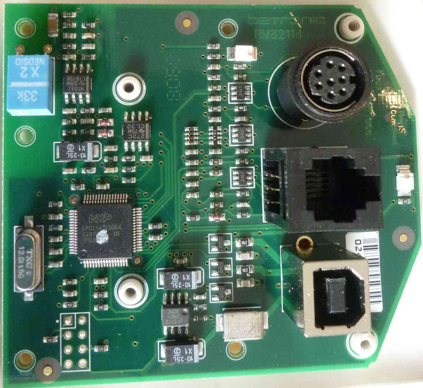
The T1904 and T1932 can handle both cable based brake types: magnetic brakes and the motor brakes (but for some reason not the old T1601 magnetic brake). Once, the protocol was developed to handle the Fortius motor brake via a serial communication the head units emulates the data frame of the serial communication, when the head unit is connected to a magnetic (eddy current) brake. Beside the case color (light blue, light lemon green) and the different USB id (3561:1904 and 3561:1932), there is (as far as I know) NO difference between T1904 and T1932 head units.
The newer head units do not longer use a AN2141 (EZ-USB) processor. Instead, they use an NXP LPC2141 (FBD64) with 32 kB Flash, 8 kb RAM and 2 kB USB RAM Link.
If the head unit is not connected to a magnetic brake, or the brake is not powered, the head unit sends 24 byte frames. When connected to a (powered) magnetic brakes, every received frame is 64 bytes long. So, even if you do not send any commands to the head unit, the head units sends 64 byte frames.
When sending 64 bytes, the checksum byte # 47 has a static value of 0x55. Byte #48 has static value 0x64. Bytes 49..63 are zeros.
If there is no steering connected the head units sends a little higher default value (0x0a0d = 2573). When connected the steering values typically are between 0x300 (full right) and 0x500 (full left). Byte #46 changes to a fixed value of 0x02 after sending ANY data to the head unit. So this value do not longer 'bounces' the 'mode' value of a run command.
Bytes #40, 41 is the 'bounced' value of the 'load' value of a run command. Idling, bytes #36,37 and bytes #38,39 are 0x040f.
The communication between the head unit and the Fortius motor brake is a serial 3.3V 'TTL' signal (not RS232) with 19200 baud and 8N1 coding. Note: the used timer on the EZ-USB can only generate a 18750 baud signal.
WIP
This chapter explains the (un)marshalling and the checksum computation together with some additional information. The description of commands and answers is a little outdated and is better described above.
# The command- and answer-frames all look like: "4-bytes-header" | Message-Payload-Data | "2-bytes-checksum"
# the length of the msg is coded in the second byte of the header (header[1])
# Before sending to the serial line, the whole frame is converted into 'readable' Hex-Values (ascii 0-9,A-F).
#
# motor brake "version" command: (cmd=0x02, no message date)
# 02 00 00 00
#    => T1941 brake sends a short version message. i.e.:
#
#     T1941[16+2]: 03 0c 00 00 65 09 00 00 ba c4 77 18 08 0c 00 00 [c4 70]
#                  |--part1--| |--part2--| |--part3--| |--part4--|
#
# part1: Header 03=response, 0xc size of packet (here 12 bytes of part2,part3,part4)
# part2: Firmware version, little endian, here "0.0.9.65"
# part3: Serial of YOUR motor brake (not the head unit), little endian, here 0x1877c4ba = 41.05.02330
#        =>  41 (brake type=1941) 05 (year) 02330 (MY motor brake serial)
# part4: unknown additional version
#
# Note: If you send 0x02,0x00,0x00,0x00 as first command or
# while switching on the brake, the brake initialize not
# all parts in the buffer and sends the following answers
# While switching on 1-2 times (raw):
#
#    01 46 46 30 32 30 30 30 30 43 44 46 46 39 44 38 31 17
#       => ff 02 00 00 cd ff [checksum: 9d 81] (decoded)
#
# and then (raw):
#
#     [01] 30 33 30 43 30 30 30 30 36 35 30 39 30 30 30 30
#          41 42 43 34 37 37 31 38 30 38 30 43 00 00 00 00
#     [Checksum: 44 46 36 42] [17]             ^^^^^^^^^^^
#                                              |||||||||||
#
# Instead of converted zeros "30 30 30 30" the brake sends
# real zeros "00 00 00 00"
# A (valid) checksum is calculated based on "00 00 00 00".
#
# After sending a 'normal' command with a 'longer' answer
# this part of the answer contains 'valid' ascii-hex values
# (probably the unchanged values of the previous 'longer'
# command)

#
#
# standard motor brake command:
#  0  1  2  3    4        5      6  7      8              9       10            11
# 01 08 01 00 LOAD_LSB LOAD_MSB 00 00 CAD_BOUNCE(0x01) WEIGHT CALIBRATE_LSB CALIBRATE_MSB
#    => with LOAD ie 0x0680 and CALIBRATE = 0x0410
#    => long answer from brake
#     T1941[24+23+1]: 03 13 02 00 00 00 00 00 00 00 f0 61 00 00 00 00 80 06 00 00 00 00 02 [e5] // one byte checksum fragment
#     T1904[24+40]:   03 13 02 00 00 00 00 00 00 00 00 00 0f 04 0f 04 43 a8 00 00 00 00 02 55 64 [00...] // checksum always 0x55 0x64
#     T1932[24+40]:   TODO
#
# illegal message (a possible test message to detect motor brake):
# 01
#    => the middle part and the checksum can vary
#     T1941[6+2] : ff 02 14 00 ce ff [48 4d]    -> little endian is 02FF, 0014, FFCE [cksm]
#     T1904[24+49]  : normal answer
#     T1932[24+40]:   TODO
#
; initial motor brake command:
; 02 00 00 00
; Answer
;   T1942/T1941[24+16+2]: 03 0c 00 00 65 09 00 00
;                           ba c4 77 18 08 0c 00 00 [c4 70]
;   T1904[24+40]:           03 0c 00 00 02 19 00 00
;                           00 00 00 00 00 00 00 00 35 69
;                           00 00 00 00 02 55 64 [00...]
;
; ================================================================
;
; CALIBRATE adds/reduce the resistance to compensate the
; friction of the system in Force-Mode
;
; TTS4 default calibration is 0x0410 = 1040 = 80*13 (or 8*130)
;
; The Tacx TTS4 software does the calibration at 20 kph
; (selectedLoad = 0x16a3).
; If the 'gauge' of the calibration screen is perfect in the
; "green" middle of the calibration bar, then TTS4 sets the
; calibration value to 0x0492 (= 90*13)
;
; How to find the calibration value without starting the TTS4
; software:
; The calibration value is exactly the negated value you can
; read as "currentLoad" (Byte# 38 and 39 in a 48 bytes data
; frame) when running the calibration at 20 kph.
; For example: You start the calibration for 20 kph and the
; average load is about 0xfb70 then
;  => 0x10000-0xFB70 = 0x490
;  => rounded to multiples of 13 this is 0x492
;
; ================================================================
;
; PEDALSENSOR_ECHO:
;     necessary? -> set Bit 0 (=0x1) to echo the pedal-sensor
;     event from bit 0 of byte 42 of brake answer frame
;
Before transferring the data to the Fortius brake, the head unit marshalls the data frame and adds a checksum.
Every frame starts with 0x01 and ends with 0x17.
Every byte is recoded into a Hexcode before going on the wire. So every byte needs two bytes on the serial. Every byte is splitted into 4 bit nibbles and converted to ASCII (characters '0'-'9' and 'A'-'F'). The only exception is the start and end byte (0x01,0x17). They are sent raw.
Python code is:
def hex2bin(b):
    if b >= 0x30 and b <= 0x39:
        # '0'..'9'
        return b - 0x30
    elif b >= 0x41 and b <= 0x46:
        # 'A'..'F'
        return b + 10 - 0x41
    elif b >= 0x61 and b <= 0x66:
        # 'a'..'f'
        return b + 10 - 0x61
    # Fallback to handle case with wrong initialized brake
    elif b == 0x0:
        return 0
    else:
        raise NameError("only Ascii Hex chars allowed")

def bin2hex(b):
    if b >= 0 and b < 10:
        return b + 0x30      # '0'
    elif b >= 10 and b < 16:
        return b - 10 + 0x41 # 'A'
    else:
        raise NameError("only 4bit nibbles allowed")
There is a 16 bit checksum at the end. (after 'hexcoding' the checksum needs 4 bytes on the wire). The checksum includes the 0x01 start frame byte, but not the end frame byte.
Python code is:
def parity16(b):
    b ^= b >> 8
    b ^= b >> 4
    b &= 0xf
    return (0x6996 >> b) & 1

def checksum(buffer):
    shiftreg = 0x0000
    poly = 0xc001
    for a in buffer:
        tmp = a ^ (shiftreg & 0xff)
        shiftreg >>= 8

        if parity16(tmp):
            shiftreg ^= poly

        tmp ^= tmp << 1
        shiftreg ^= tmp << 6

    return shiftreg
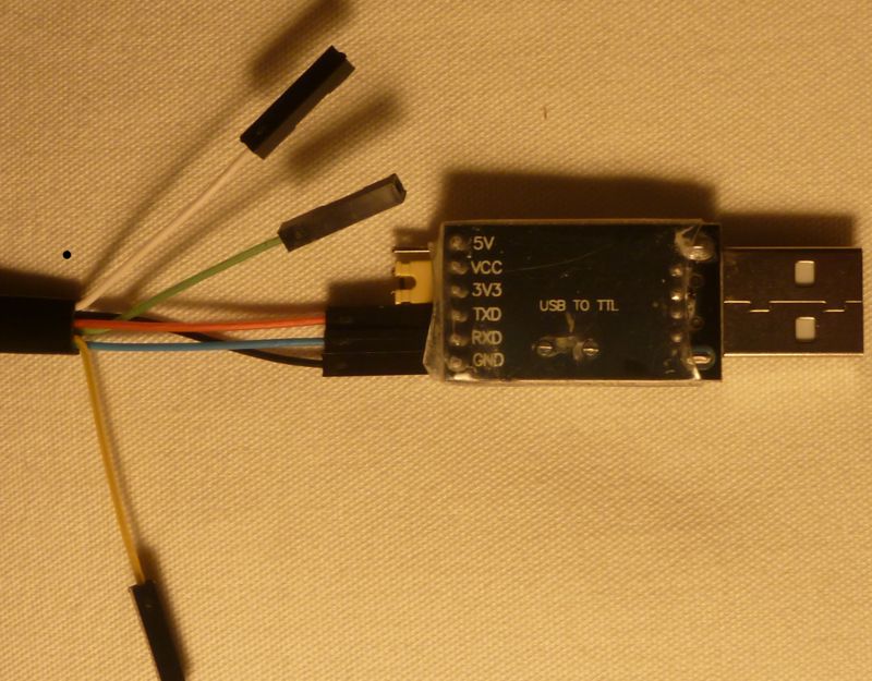
If you have a motor brake, you can build your own controlling device instead of using a Tacx head unit.
It is HIGHLY recommend to use 3.3V TTL logic, because the brake is very probably not 5V tolerant
I tried it with a (standalone) Raspi W Zero and with a 1$ CH341 budget USB2TTL device. I should also work with FTDI RS232R or CP2102 bases adapters, as long as they have 3.3V signal level.
If you do not like to solder or crimp your own cable:
From 'Makeblock' there is a cable with a RJ12/RJ25 (6p6c) socket on one side an Dupont sockets on the other side. Price is about 2$-3$ for a bundle with two cables. The Makeblock part no. is MB14230. They even use the same wire colors as the original cable.
The cable is only 20cm long, but with a full connected (straight through) female-female 6p6c coupler (i.e. from "inLine" part no. 69999 EAN: 4043718012909 or from "Goobay" part no. 50592 EAN: 4040849505928), you can use the original cable in addition
Alternatively, you can also use a USB extension cable.
Just wire USB/TTL-GND to RJ12-Pin 2 (black, GND), USB/TTL-Tx to RJ12-Pin 3 (Red, Host-Tx, Brake Rx) and USB/TTL-Rx to RJ12-Pin 6 (blue, Host-Rx, Brake Tx).
Set permissions for '/dev/ttyUSBx' where 'x' is YOUR serial USB->serial adapter
=> typically /dev/ttyUSB0 if you have only one adapter connected to your PC

1. solution: every time after you plugged in the adapter (here: /dev/ttyUSB0)
  sudo chmod 666 /dev/ttyUSB0

2. solution: add your user to the group, that 'owns' the ttyUSB device (typically 'dialout')
  sudo adduser $USER dialout

3a. solution: add a rule (here for everyone!) to /etc/udev/rules.d/ i.e. '99-myttyusb.rules' with
  KERNEL=="ttyUSB[0-9]*",MODE="0666"

3b. only for a specific adapter (here: 1a86:7523 QinHeng Electronics HL-340 USB-Serial adapter)
  ACTION=="add", KERNEL=="ttyUSB[0-9]*", ATTRS{idVendor}=="1a86", ATTRS{idProduct}=="7523", MODE="0666"
On Raspi GND is Pin 6, Tx is Pin 8 and Rx is Pin 10.
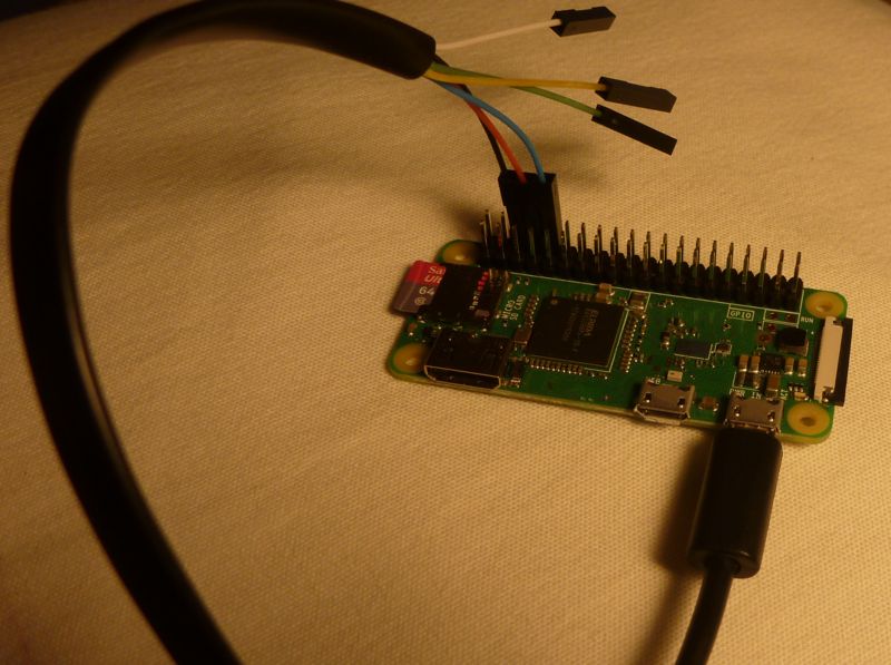
# If you connect the brake directly to Raspi's GPIO 14 and GPIO 15 (that is Pin 8 (Tx) and Pin 10 (Rx))
# do no forget to make the UART accessible via /dev/ttyAMA0 by adding:
#     enable_uart=1
# to your /boot/config.txt.
#
# On Raspi 3 B (or B+) or Raspi Zero W use /dev/ttyS0 (not /dev/ttyUSB0 or /dev/ttyAMA0). Be warned:
# the Mini-UART on the Raspi W Zero is limited and the error rate increases with a high command rate.
# So, if you do not need on-board Bluetooth, switch it off with
#     dtoverlay=pi3-disable-bt
# (/boot/config.txt) to enable the standard UART under /dev/ttyAMA0.
# If you need Bluetooth on the Raspi, I recommend to use an additional USB2TTL adapter instead of the
# Mini-UART.
#
# I recommend to first test the serial adapter with a simple loopback test before
# you connect the brake just to make sure the you talk to the serial via /dev/ttyAMA0.
# Calling "./ttyT1941.py -d /dev/ttyAMA0" (in loopback) should print something like
#   Using /dev/ttyAMA0
#   bytearray(b'\x02\x00\x00\x00')
#   bytearray(b'\x02\x00\x00\x00')
#
All devices are using the default ANT+ network key. The default key is set after a reset of the ANT dongle. Please send a ANT reset command to the USB dongle to (re)set all you networks to the default network key.
Tacx brakes and the other Tacx devices are using several different ANT channels, periods and device types.
| Tacx Device Name | ANT Device-Type (*1) | Channel frequency | Channel period | =Hz | Notes |
|---|---|---|---|---|---|
| (i)Vortex Brake | 0x3d | 66 = 0x42 | 0x2000 = 8192 | 4 Hz | GoldenCheetah has demystified the protocol. Check i.e. ANT.h and ANTMessage.cpp |
| Vortex Display | 0x3e | 78 = 0x4e | 0x0f00 = 3840 | ~8.53 Hz | T2172 light-blue, T2162 yellow-green |
| Bushido Brake | 0x51 | 60 = 0x3c | 0x1000 = 4096 | 8 Hz | pyBushido and Cyclismo both have demystified the protocol |
| Bushido Display | 0x52 | 60 = 0x3c | 0x1000 = 4096 | 8 Hz | hosts sends 4E #ch# AC commands |
| Genius Brake | 0x53 | 60 = 0x3c | 0x1000 = 4096 | 8 Hz | |
| Blacktrack Steering | 0x54 | 60 = 0x3c | 0x0800 = 2048 | 16 Hz | Steering T2420. Probably also NEO track T2430. Slave => Master: Keep alive ? [01 00 00 00 00 00 00 00] ? steering |
| Cursor Control (Genius interface) | 0x55 | 60 = 0x3c | 0x1000 = 4096 | 8 Hz | T2022, The small blue round controller |
| Flux Brake | 0x56 | 66 = 0x42 | 0x2000 = 8192 | 4 Hz | TTS4 knows this device, but maybe it was never released (with legacy ANT protocol) Keepalive / Control messages from host to brake: host sends: 4E #ch# 10 00 00 aa 7e 00 00 00 |
| Flow Brake | 0x5f | 66 = 0x42 | 0x2000 = 8192 | 4 Hz | Same as Flux Brake: see above |
Note *1: With ANT+ Pairing Bit add 0x80 to the ANT Device-Type
All older Tacx ANT+ devices handle at least the 3 commands. A command always starts with "0xAC" followed by the command number. All answers start with "0xAD" followed by the command number, followed by the payload.
| Host Cmd Nr | type | Data from Host | Answer (example) | note |
|---|---|---|---|---|
| 01 | Get Device Serial | ac 01 00 00 00 00 00 00 | ad 01 01 0c 00 00 25 78 | Big endian: "01"=20 ("00"=19??), "0c"=12 year of production, "00 00 25 78" is MY serial => 20-12-09592 |
| 02 | Get SW Version | ac 02 00 00 00 00 00 00 | ad 02 01 01 01 e9 00 00 | Big endian: here 01.01.01e9 = 1.1.489 |
| 04 | Battery Status | ac 04 00 00 00 00 00 00 | ad 04 03 xx xx xx xx xx | Here 03 = OK, xx xx xx xx xx contains data from the last command |
| Status | Value | Notes |
|---|---|---|
| New | 1 | |
| Good | 2 | |
| OK | 3 | |
| Low | 4 | |
| Critical | 5 | |
| Charging | 6 | Not used? |
| unknown | 7 |
Every devices send regular data pages.
| Byte | 0 | 1 | 2 | 3 | 4 | 5 | 6 | 7 |
|---|---|---|---|---|---|---|---|---|
| Value | 00 | HR? | [0000LDRU] | 0xFF | 00 | 00 | 00 | 00 |
Byte 1: (not confirmed): Heart rate, if device receives heart beats from a (non coded, 5.3 kHz) heart rate belt.
Byte 2 contains a 4 bit (OR-ed) value in bits 0-3. Bits 4-7 are always zero.
| Bit Nr. | Bitmask value | meaning |
|---|---|---|
| 0 (U) | 0x01 | Up |
| 1 (R) | 0x02 | Right |
| 2 (D) | 0x04 | Down |
| 3 (L) | 0x08 | Left |
Of course, if you turn the control device by 90, 180 or 270 degrees, the meaning of the bits are turned, too.
| Byte | 0 | 1 | 2 | 3 | 4 | 5 | 6 | 7 |
|---|---|---|---|---|---|---|---|---|
| Value | 00 | [HH] | [LL] | FF | 00 | 00 | 00 | 00 |
HH ist the high byte and LL ist the low byte of a signed 16 bit steering value. My BlackTrack steering shows values between 0xFE50 and 0x01e0. Zero is at about 0x0040.
To prevent the steering to stop sending data pages while not used, the host (probably) needs to send some kind of keep alive data frame (0x01 0x00 0x00 0x00 0x00 0x00 0x00 0x00).
Not much to describe here. The brake talks standard ANT FE-C