A lab report by Vini Tripathii
https://github.com/ut33/IDD-Fa18-Lab1/blob/master/IMG-1149.JPG (LED ON) https://github.com/ut33/IDD-Fa18-Lab1/blob/master/IMG-1150.JPG
a. What color stripes are on a 100 Ohm resistor? The color stripes on a 100 Ohm resistor is Brown (1), Black(0), Brown(1), Gold. This correlates to the digits 10 with a multiplier of 10 -- 100. The gold indicates the tolerance (+-5%). The color stripes on a 220 Ohm resistor (as used in the lab) is Red(2), Red(2), Brown(1), Gold. Likewise, this correlates to 22 * 10 with a tolerance of +-5%.
b. What do you have to do to light your LED? In order to light the LED I had to press the switch. While the switch was pressed, the LED was on. When the switch was not pressed, the circuit to the LED was broken (switch button not pressed => open switch =>infinite resistance) and the LED turned off. https://www.youtube.com/watch?v=uEe2CwbTuH0
a. What line(s) of code do you need to change to make the LED blink (like, at all)? The following lines correlate to the LED blinking.
digitalWrite(LED_BUILTIN, HIGH); // turn the LED on (HIGH is the voltage level)
delay(1000);
digitalWrite(LED_BUILTIN, HIGH); // turn the LED off by making the voltage LOW
delay(1000);
https://www.youtube.com/watch?v=YMo-yQ4u4FM
b. What line(s) of code do you need to change to change the rate of blinking? To change the rate of blinking, change the delay amount within the void loop section. The unit is miliseconds. For example, in the above code, the LED stays on for a second, then turn off for a second, then on again, and so forth. If the delay was reduced, the LED would blink much faster.
c. What circuit element would you want to add to protect the board and external LED? To protect the circuit elements it was crucial to add a resistor. The resistor used in this lab was the 220 Ohm. https://www.youtube.com/watch?v=NCy-g9eBrSw
d. At what delay can you no longer perceive the LED blinking? How can you prove to yourself that it is, in fact, still blinking? When the delay is 20 miliseconds or less, it just appears to be on. To test whether the LED was actually blinking or not I included a print line to the serial monitor: Serial.print("on"). Likewise, when the LED was set to low, it was supposed to print Serial.print("off"). As shown in the video, the LED appears on but is actually blinking.
e. Modify the code to make your LED blink your way. Save your new blink code to your lab 1 repository, with a link on the README.md.
In my iteration of the blink code, I change the rate of blinking of the LED. The delay starts at 5 miliseconds, and doubles each iteration of the loop until it is more than or equal to 2000 miliseconds.
Make a video of your LED blinking, and add it to your lab submission.
https://www.youtube.com/watch?v=jPymoCGKBSc
a. Are you able to get the LED to glow the whole turning range of the potentiometer? Why or why not? No, before the potentiometer is completely turned, the LED already is off. This is because the threshold of voltage required for the LED to turn on is higher than the lowest value from the potentiometer. Thus the LED turns off before the potentiometer completely turns. https://www.youtube.com/watch?v=vGilHgE4GAI https://www.youtube.com/watch?v=H-sZqCj8iE4
a. What do you have to modify to make the code control the circuit you've built on your breadboard? There are three variables of interest to control the fade code. Most important is to make sure the pin number aligns with LED placement on the board. Then the intial value for 'brightness' and 'fadeAmount' affect the rate of fading.
https://www.youtube.com/watch?v=m7nXKec2ko4
b. What is analogWrite()? How is that different than digitalWrite()? analogWrite() is the analog equivalent of the digitalWrite() method. Whereas digitalWrite has only two possible types of outputs (HIGH and LOW), analogWrite() can give a range of different possible outputs.
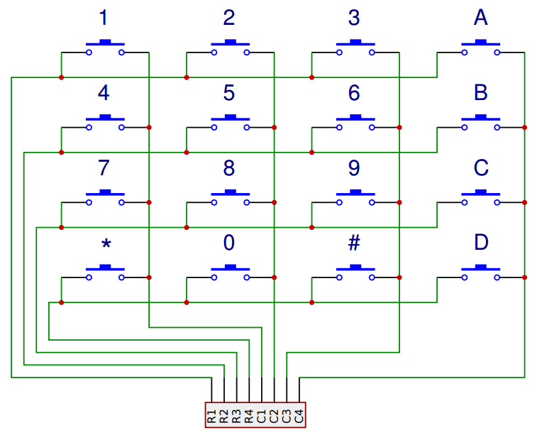
Here is a circuit diagram of a matrix membrane keypad. http://www.circuitbasics.com/wp-content/uploads/2017/05/Arduino-Keypad-Tutorial-4X4-Keypad-Schematic.png
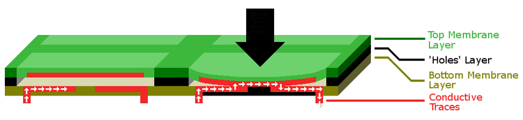
https://www.14core.com/wp-content/uploads/2015/07/750px-Membrane_keyboard_diagram_FULL_SCALE.png
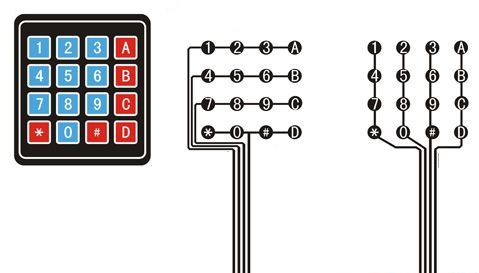
https://www.14core.com/wp-content/uploads/2015/07/Keyboard-Membrain-arduino-module.jpg
Sources: http://www.circuitbasics.com/how-to-set-up-a-keypad-on-an-arduino/ and https://www.14core.com/using-membrane-keypadkeyboard-on-arduino/
a. Is there computation in your device? Where is it? What do you think is happening inside the "computer?" There is no computation per se occuring in the keypad.
b. Are there sensors on your device? How do they work? How is the sensed information conveyed to other portions of the device? There are sixteen keys in the keypad (although half are broken). Beneath every key is a switch. Every switch in a row is connected to the other switches in that row. Likewise, every switch in the same column is also connected by a conductive trace. The identity of the buttons come from the intersection of the row and column that forms their location. When no buttons are being pressed the rows are held LOW while the columns are HIGH. When the button is pressed, the corresponding column is pulled low. The arduino tests the rows, setting them to HIGH until the relevant key is also pulled high. This allows the arduino to determine the identity of each key.
c. How is the device powered? Is there any transformation or regulation of the power? How is that done? What voltages are used throughout the system? The keypad does not require external power. In essence, it is a soft flat matrix of switches.
d. Is information stored in your device? Where? How? Information is not stored, but the pressing of different keys can be sensed in real-time.
2. Using your schematic, figure out where a good point would be to hijack your device and implant an LED.
The keypad was connected to the arduino metro mini. The circuit diagram can be seen in following photo. https://github.com/ut33/IDD-Fa18-Lab1/blob/master/IMG-1191.JPG
When 1 is pressed the LED turns on. When 2 is pressed the LED turns off. When 4 is pressed the LED blinks slowly. When 5 is pressed the LED blinks fast. https://www.youtube.com/watch?v=7irzLs5omKI