This page walks through how to move bytes back and forth between a PC and MCU. For instructions setting up the development environment and running a simple microcontroller program, please see the previous tutorial.
All Nucleo development boards come with integrated programmers (for the L432KC, this is located on the bottom). This is a diverse chip, with the ability to flash new code into the MCU, debug code running on it, and also bridge UART communication on the MCU side with USB communication on the PC side. Essentially, the microcontroller can send bytes via UART, and the programmer chip will convert it to a USB packet and send it to the PC. The USB protocol defines a software interface called a virtual COM port (VCP) which allows an application to interact with a device as though it were streaming raw bytes. Serial monitor programs such as Docklight can then display these raw bytes to a user, perhaps formatted as human-readable strings. The same idea holds for sending messages to the microcontroller from the PC.
Later tutorials on FreeRTOS will build on top of this one.
For this walkthrough, we will either need a serial terminal program or a custom script that sends and receives bytes via virtual serial port (e.g. PySerial). A popular cross-platform serial terminal is PuTTY. One that works nicely for Windows and provides a rich GUI is Docklight (download: https://docklight.de/downloads/). We will use Docklight in this tutorial.
Continuing from the last tutorial, our project should be all set up. In fact, the default peripheral initialization already enables the USART which is connected to the programmer, USART2.
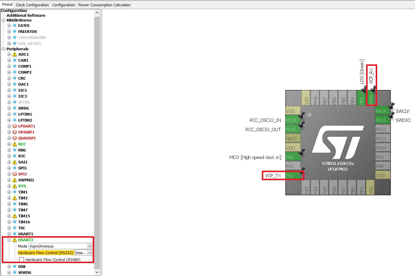
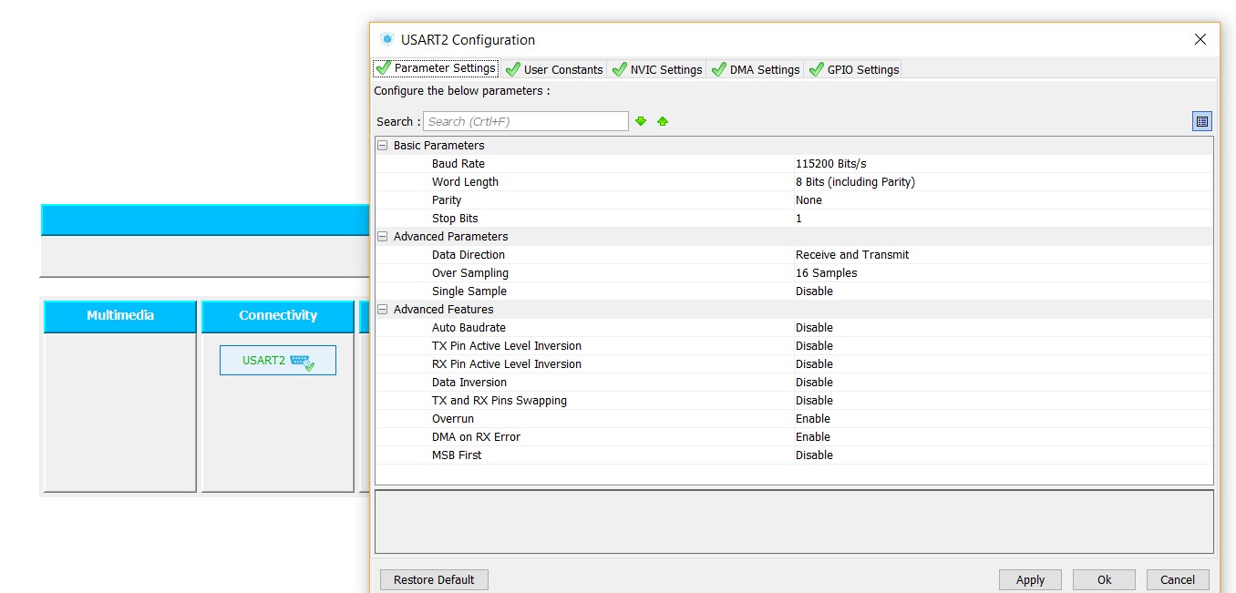
Opening up the USART2 window from the Configuration tab shows us all the settings we can manipulate for this peripheral. It is of key importance that both the sender and the receiver agree on the baud rate, word length, parity, and number of stop bits, so we will need to remember to set up the PC program with the exact same parameters. For now, we will stick with the default of 115200 8-N-1, meaning baud rate of 115200 symbols per second, 8-bit word length, no parity, and 1 stop bit.
Also in the USART2 window, we will enable interrupts from the NVIC Settings tab and enable TX and RX DMA channels from the DMA Settings tab. We will see the differences between polled IO, interrupt-based IO, and DMA-based IO in this tutorial.


We can then generate the code as before.
The HAL_UART_Transmit() function is the blocking API for sending bytes via UART. We'll show how to use it first then make a few important points after.
const uint32_t timeout = 10; // ms
char msg[] = "Hello world!";
while (1)
{

/* USER CODE END WHILE */

/* USER CODE BEGIN 3 */
    HAL_UART_Transmit(&huart2, (uint8_t*)msg, sizeof(msg), timeout);
    HAL_GPIO_TogglePin(LD3_GPIO_Port, LD3_Pin);
    HAL_Delay(500);
}
Important points:
- huart2 is an auto-generated struct which the HAL UART APIs use to manage transfer requests. If we were to have enabled USART1 in Cube, we would be able to use the huart1 handle in the exact same way
- When the
HAL_UART_Transmit()function is called, the function is not exited until (1) all the bytes passed in have been sent, or (2) thetimeoutperiod has elapsed. This is typical of blocking I/O, and it really wastes CPU resources! Consider this: according to the Clock Configuration tab in Cube, the microcontroller's CPU is running at 32 MHz (HCLK). Assuming the 3-stage pipeline in the ARM M4 processor is flowing nicely, 32 million instructions can be executed per second (32 ns per instruction). Well, at a baud rate of 115200, and with 10 bits sent per word (1 start bit + 8 data bits + 1 stop bit), it takes about 87 us to send one byte via UART. In that 87 us, the CPU could have executed about 2700 instructions. "Hello world!" is 13 bytes including the null character, meaning that sending it via blocking I/O wastes about 35000 instructions worth of processing time.

The HAL_UART_Receive() function is the blocking API for receiving bytes via UART. In this example, we'll change the LED state from the PC by sending either 0 or 1 as ASCII.
const uint32_t rx_timeout = UINT32_MAX; // ms
const uint32_t tx_timeout = 10; // ms
const char err_msg[] = "Invalid character. Please enter 0 or 1\n";
uint8_t ascii_value;
uint8_t int_value;
while (1)
{

/* USER CODE END WHILE */

/* USER CODE BEGIN 3 */
    HAL_UART_Receive(&huart2, &ascii_value, 1, rx_timeout);

    int_value = ascii_value - '0';
    if(int_value > 1){
        HAL_UART_Transmit(&huart2, (uint8_t*)err_msg, sizeof(err_msg), tx_timeout);
        continue;
    }

    HAL_GPIO_WritePin(LD3_GPIO_Port, LD3_Pin, (GPIO_PinState)int_value);
}
Important points:
- The program does not do anything until a byte is received, hence the maximum RX timeout. That is the sad reality of blocking I/O
- We call the variable
ascii_valuea buffer
Suppose we would like to be able to send "Hello world!" to the PC twice per second while also being able to change the LED state by sending a command from the PC. If we were only able to use polled I/O, we would not be able to accomplish this reliably as we would be constrained to transmit and receive at separate times. To get around this, we use the interrupt-based APIs HAL_UART_Transmit_IT() and HAL_UART_Receive_IT(). Both of these functions will initiate a transfer of bytes, then return and allow the CPU to continue executing instructions from the caller's context. Basically, the CPU operates in parallel with the UART hardware while it sends a single byte. When the byte is done being transmitted, the UART hardware generates an interrupt, and the auto-generated interrupt handler will load the next byte into the UART hardware, and the cycle begins again.
Since HAL_UART_Receive_IT() returns immediately after being called, we need a way of checking whether it it is done before using the buffer. This can be done by polling the UART handle's state in our application loop, or by means of a callback. We'll look at the former option first, and will use the latter option when we go through DMA.
const uint32_t tx_timeout = 10; // ms
const char tx_msg[] = "Hello world!";
uint8_t ascii_value;
uint8_t int_value;
uint32_t lastRunTime = HAL_GetTick();
uint32_t curTime;

HAL_UART_Receive_IT(&huart2, &ascii_value, 1);
while (1)
{

/* USER CODE END WHILE */

/* USER CODE BEGIN 3 */
    if(huart2.RxState ==  HAL_UART_STATE_READY){
        // If we are here, the reception initiated previously is complete
        int_value = ascii_value - '0';
        if(int_value <= 1){
            HAL_GPIO_WritePin(LD3_GPIO_Port, LD3_Pin, (GPIO_PinState)int_value);
        }

        HAL_UART_Receive_IT(&huart2, &ascii_value, 1);
    }

    curTime = HAL_GetTick();
    if(curTime - lastRunTime > 500){
        // Event triggered every 500 ms
        lastRunTime = curTime;
        HAL_UART_Transmit(&huart2, (uint8_t*)tx_msg, sizeof(tx_msg), tx_timeout);
    }
}
When we run this program, we will see "Hello world!" printed in our serial monitor twice per second, and we will notice the system also responds reliably to LED commands '0' and '1'.
Important points:
- Interrupt-based APIs allow us to initiate data transfers in parallel with each other and with the CPU. For a UART, such transfers are constrained to the length of a byte, so after a byte is sent or received, the CPU is interrupted for a brief period of time to handle the event. This is a huge improvement compared to the blocking I/O cases illustrated above, as now the system can go do other things. Usually, interrupts occur infrequently relative to the core operating frequency, and interrupt handling code is small
- The
HAL_GetTick()returns the number of ms the program has been operating for (this is tracked by the "SysTick" hardware timer, which is always running). We can use this to time-trigger events
The DMA controller is a module completely distinct from the CPU. The CPU talks with the DMA controller to initiate data transfers of several bytes long, in general. Once the CPU performs this initial step, the DMA controller performs the entire transfer itself, and notifies the CPU via interrupt once it is entirely done. Imagine a scenario where you have 5 UARTs sending and receiving several bytes simultaneously at 1 Mbps. This would generate a ton of interrupts, causing the CPU to be frequently diverted from the application code. DMA has an obvious advantage in this case since the CPU is only needed at the start and the end of transfers. One caveat is that the CPU and DMA controller have to share the system bus to access memory, so if the CPU is involved in memory-intensive tasks the bus contention may cause a slowdown.
The UART DMA APIs are very similar to the others for the most part. Sending uses HAL_UART_Transmit_DMA() and receiving uses HAL_UART_Receive_DMA(). One difference of note is that these can be configured to use circular buffering. For example, if circular receive is used, then calling HAL_UART_Receive_DMA() will cause bytes to be read from the RX line into the buffer forever. This is good in cases where an unknown amount of data needs to be received or where the application must continuously be subscribed to the RX line.
There's no reason why we can't just replace the HAL_UART_Transmit_IT() call in the example above with HAL_UART_Transmit_DMA, and similarly for the receive functions, but we also mentioned earlier that we can use a callback instead of polling the UART handle state. So Let's check that out. First, open up stm32l4xx_hal_uart.h and scroll down to the functions whose names end in "Callback".

These functions are all declared __weak which means they won't be compiled into your code unless you provide an implementation for them. If you do provide an implementation, they'll automatically be called due to the magic of how HAL works. For example, if we implement HAL_UART_RxCpltCallback(), then whenever the reception we initiate is complete, that function will be invoked and our custom implementation will be executed.
Let's also enable circular receptions for the RX DMA stream (remember to generate the code after making this change!).

/* Private variables ---------------------------------------------------------*/

/* USER CODE BEGIN PV */
static uint8_t ascii_value;
/* Private variables ---------------------------------------------------------*/
...
int main(void){
    ...
    uint32_t lastRunTime = HAL_GetTick();
    uint32_t curTime;
    const uint32_t tx_timeout = 10; // ms
    const char tx_msg[] = "Hello world!";

    HAL_UART_Receive_DMA(&huart2, &ascii_value, 1);
    while (1)
    {

  /* USER CODE END WHILE */

  /* USER CODE BEGIN 3 */
        curTime = HAL_GetTick();
        if(curTime - lastRunTime > 500){
            lastRunTime = curTime;
            HAL_UART_Transmit(&huart2, (uint8_t*)tx_msg, sizeof(tx_msg), tx_timeout);
        }
    }
  /* USER CODE END 3 */

}
...
/* USER CODE BEGIN 4 */
void HAL_UART_RxCpltCallback(UART_HandleTypeDef *huart){
    if(huart == &huart2){
        uint8_t int_value = ascii_value - '0';
        if(int_value <= 1){
            HAL_GPIO_WritePin(LD3_GPIO_Port, LD3_Pin, (GPIO_PinState)int_value);
        }
    }
}
/* USER CODE END 4 */
Important points:
- Since we are using circular DMA, we only need to initiate the reception once. In a real-world situation, you'd probably want to implement the error callback to restart the transfer if there were communication errors
- The reception event processing can all be moved into the callback, which more closely resembles how we envision the system's operation in an abstract sense
In the previous example, we saw how DMA allows us to stay continuously subscribed to a source of information while at the same time offloading the CPU's involvement in the communication process. The DMA channel CNDTR register tells us (indirectly) how many bytes have been received into the buffer. Specifically, it is a downcounter which starts at the transfer size passed into HAL_UART_Receive_DMA() as the third argument, and each time a new byte is received it is decremented. When CNDTR equals 1, the next reception will cause it to wrap around the number line back to its initial value. In this way, reception can continue forever and applications can treat the receive buffer like a FIFO.
const char tx_msg[] = "Filled the buffer";
uint8_t rx_buff[92];
uint16_t num_bytes_received;

HAL_UART_Receive_DMA(&huart2, rx_buff, sizeof(rx_buff));
while (1)
{

/* USER CODE END WHILE */

/* USER CODE BEGIN 3 */
    num_bytes_received = sizeof(rx_buff) - huart2.hdmarx->Instance->CNDTR;

    if(num_bytes_received == sizeof(rx_buff) - 1){
        HAL_UART_Transmit_DMA(&huart2, (uint8_t*)tx_msg, sizeof(tx_msg));
    }
}
Important points:
- Once again, the error callbacks should be implemented or the UART handle's state should be checked periodically to make sure communication errors can be recovered from
- In a real application, the circular buffer would probably be checked on a time-triggered basis, or the idle line interrupt would be used to trigger a check