Wiring of a 4x4 Keypad built using Arduino in TinkerCAD
A keyboard matrix circuit is a design used in most electronic musical keyboards and computer keyboards in which the key switches are connected by a grid of wires, similar to a diode matrix. This kind of keypad is mostly seen on microwave owens, gas pumps and Calculators.
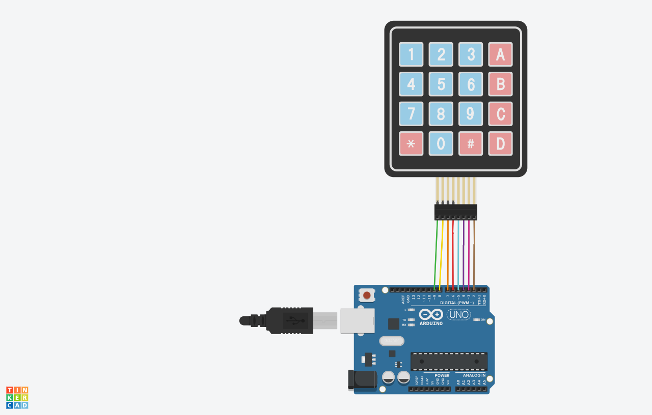
8 wires arranged in 4 rows and 4 columns can connect 16 keys. There is a special membrane switch beneath each key. All these membrane switches are connected to each other with conductive trace underneath the pad forming a matrix of 4×4 grid. If you had used 16 individual push buttons, you would have required 17 input pins (one for each key and a ground pin) in order to make them work. However, with matrix arrangement, you only need 8 microcontroller pins (4-columns and 4-rows) to scan through the pad. By scanning the crossings, a microcontroller determines which keys are currently being pressed.
The keypad.h library is used in this model to skip continuously scanning rows and columns.
Check out the working model at: https://www.tinkercad.com/things/0IgdqGHQZev