-
Notifications
You must be signed in to change notification settings - Fork 15
Hydraulic 2D structure
Available for version 2.2.9X or later.
Hydraulic 2D structure are a hydraulic network element that represent a complete flow 2D model. As a part of a hydaulic network, its boundary conditions can be connected to other part of the network by hydraulic network link. 2D models of different type can be connected, one sending output hydrograph to other one as input.
There are two ways to add a new hydraulic 2D structure to the Lekan project:
- Create a new hydraulic structure from scratch
- Import a existing 2D flow model defined externally
To create a new Hydraulic 2D Structure, the user has to select the map tool "Structure 2D":

With this tool, the user has to delineate the domain of the model by digitizing on the map. Note that a right click on an existing vector layer polygon feature allow the user to defined the domain with this polygon.
If importing a 2D structure is possible (if at least one available simulation engine supports import), an arrow is displayed on the right of the button 
Clicking on this arrow bring up a menu with a line "Import Structure 2D". If the user choose this line, the following window appears (here for HEC-RAS):

The user can choose which simulation engine to import and simulation engine specific settings will be available.
The entry to Hydraulic 2D Structure is through the properties window of this element (see Hydraulic network).

The tool buttons on top right of the window under the name parameter allow the user to (from left to right):
- Enter in the window to edit the flow model, see Editing 2D flow model
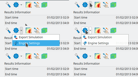
- Launch simulation, export simulation, or change settings of the simulation engine
- Change settings of scalar rendering on the map: selection of the variable, color ramp settings and mesh frame settings
- Change settings of vector field rendering: selection of the variable and vector displaying settings
- Open the 3D view.
Note that, if boundary conditions of the flow model are added / removed from the window to edit model (in "Structure page"), boundary conditions are edited from independent element properties windows. Indeed, in Lekan, boundary conditions are considered as nodes part of the hydraulic network. See Hydraulic network for more details about hydraulic network and Boundary conditions.
Properties depending on hydraulic scheme
- Simulation configuration and associated parameters
| Engine | Creation | Import | Mesh frame editing | Add/remove boundary conditions | Boundary conditions editing | Model export | Run simulation |
|---|---|---|---|---|---|---|---|
| TELEMAC | Yes | No | Yes | Yes | Yes | Yes | Yes |
| HEC-RAS | No | Yes | No | No | Yes | No | Yes |
-
Creation: User can create a new 2D flow model from scratch.
-
Import: An existing model can be imported.
-
Mesh frame editing: The mesh frame of the structure can be edited.
-
Add/remove boundary conditions: Boundary conditions can be added to the model and removed.
-
Boundary condition editing: Boundary conditions type can be changed and the condition fonfiguration can be changed.
-
Model export: The structure 2D can be exported to be run externally.
-
Run simulation: The model of the structure can be run from Lekan.
Specific documentation on the use of these engines in Lekan is provided in dedicated pages:
Depending of simulation engines, some general settings can be necessary to run simulation.

Choosing "Engine Settings" in the menu above leads to open a windows with general settings specific to the current simulation of 2D structure.
This is a side bar