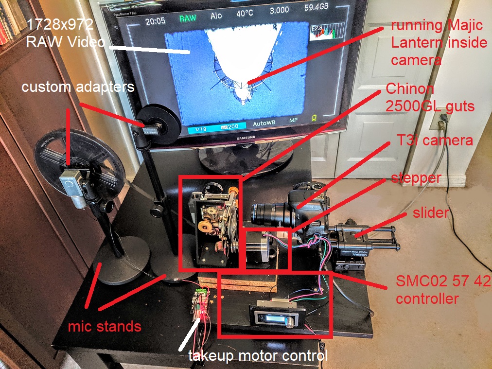
This setup consists of a modified projector and the T3i Canon camera. The setup provides the 8mm film capture running at 3FPS and outputs the video in ML (Magic Lantern) RAW format in 1728x972 resolution.
The purpose of this readme is to provide the instructions to the user on how to modify the existing 8mm film projector for the video capture directly into the camera using a small off the shelf stepper controller.
Similar to other projects of this type, this one also requires several modifications to the projector including the light change, and motor change but unlike other projects of this type it provides the DSLR camera capability and RAW video format. The DSLR is used in a slow video mode.
The stepper controller is programmed to precisely control the stepper motor rotation to provide the proper FPS which matches the FPS of the camera with no flicker.
System Components
At the heart of the system is the SMC02 stepper controller. https://www.ebay.com/itm/175028855543
Use the following stepper.
2.7A for this type motor https://www.amazon.com/gp/product/B00PNEPF5I/
Other steppers may also work but are not covered in this readme.
If you are planning to pull the projector transport out, then you can use the mounting bracket from this repo. Check the mechanical parts folder.
This pulley is recommended. You will also need a sleeve because the pulley bore is slightly larger than the motor shaft. Check t mechanical folder for the sleeve sdl. https://www.amazon.com/gp/product/B07C4QD1BV/
This used to be a big problem but with the neophrene Urethane belting that became available it is easy to make your own custom belt.
https://www.amazon.com/gp/product/B07L3W7Z1N
Follow the following instructions:
https://www.youtube.com/watch?v=mBtHvPWVgDw
Print out all of the parts from the mechanical folder. If you do not have the printer then you can get them done outside but it will become rather costly. Getting a new 3D printer will probably be cheaper in a long run.
Use a 14"x10"x0.63": piece of wood to mount the components on.
https://www.homedepot.com/p/Rubbermaid-Black-Laminated-Wood-Shelf-10-in-D-x-36-in-L-4B2500BLA/100200907
Additionally cut two additional pieces of wood size 7"x7"x0.63"and 7"x3.6"x0.63". These will be used as a standoff for the projector transport.
This will work for the Chinon 2500GL but if other type of projector is used then you will have to figure out how high the the transport has to sit for the proper alignment with the camera.
Assemble the three pieces of wood as shown.
 Mount the projector transport bracket to the base as shown.
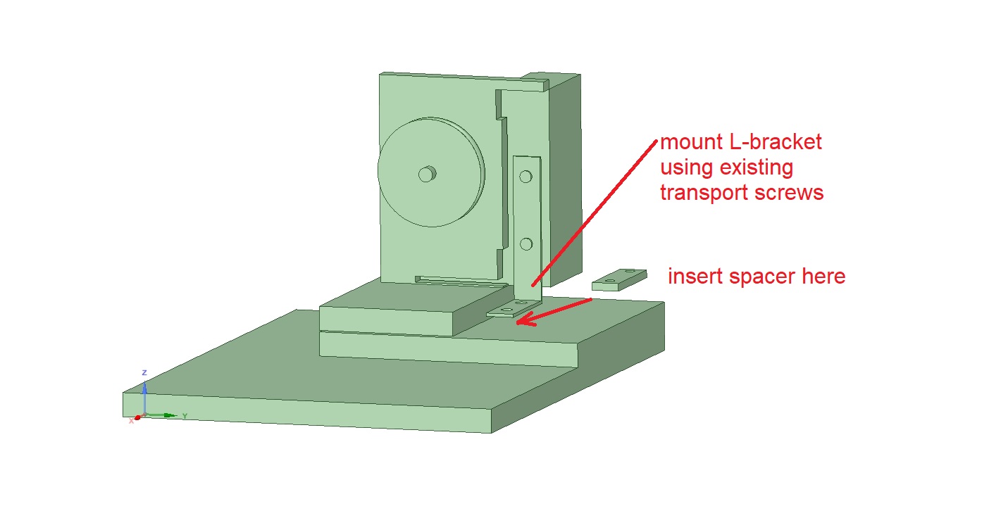
 Mount the transport onto the bracket using the original transport mounting screws.
The transport mounting will need additional support to prevent the film shake. Use an L bracket
Mount the transport onto the bracket using the original transport mounting screws.
The transport mounting will need additional support to prevent the film shake. Use an L bracket
https://www.homedepot.com/p/Everbilt-3-in-Black-Corner-Brace-4-Pack-13741/300985591
and mount it as shown. Install the spacer underneath the bracket so that the transport sits perfectly vertical. The spacer is included in the mechanical folder. If the transport is not vertical then adjust the spacer accordingly. Tilted transport will cause focus issues.
Mount the macro lens onto the camera.
Mount the camera onto the slider.
Turn the camera on and position it so that the film gate is visible and adjust the zoom so that the film gate covers most of the camera display. Set the slider knobs about half way of the travel. Now, slide the camera on the base board left and right and forward and backwards until the gate is centered in the camera display. Mark the position of the slider on the base board.
Remove the camera from the slider.
Place the slider upside down on the table and place a piece of white paper over it. Trace the outline and teh mounting holes as the first graders do.
https://craft-art.com/tracing-pictures/
Cut the outline with the scissors and place it on the board so that it is aligned with the marked up outline on the board done in the previous step. Drill the holes. Remove the paper template and mount the slider onto the board using the appropriate size screws.
Light Mounting.
The light has to be mounted in front of the gate.
(This is still work in progress -- will be updated shortly)
Takeup reel mount.
Use the microphone stand
https://www.amazon.com/dp/B07F82BPLV
Remove the microphone adapter and install the takeup motor bracket.
Mount the takeup motor onto the bracket using the M3x8 screws
https://www.amazon.com/gp/product/B076J3W7R4
Slide the takeup spindle over the motor shaft.
Slide the takeup reel over the spindle.
Install an M3 wingnut onto the M3x25 flathead screw and tighten it.
Slide a flat M3 washer over the screw shaft to create the "clutch" mechanism.
Push the screw through the spindle center until it engages with the motor shaft.
Turn the wingnut in until snug. The tightness will determine the amount of pull on the film.
You do not want it too tight becaue it can cause film damage.
Solder two wires to the motor terminals.
Connect the wires to the speed controller.
https://www.amazon.com/gp/product/B071H2YQG5/
Connect the controller to the 12VDC source.
Proceed similarly with the supply reel. Remove the mic adapter from the microphone stand. install the reel mount assembly onto the mic stand. Install the small clip onto the reel spindle using a small metal pin. https://www.amazon.com/Neiko-50412A-Assortment-Storage-Pieces/dp/B076B4WT1V/
 Controller installation
Afix the mounting bracket onto the base board by using two wood screws.
Mount the SMC02 cntroller onto the controller mount but sliding it into the mount opening all the way until locked in.
Wire up the controller as shown.

Stepper Installation
Mount the stepper onto the stepper racket using the M4 screws and nuts.
Mount the sleeve over the motor shaft and then side the pulley over the sleeve. Do not tighten the locking slugs.
Align the pulley with the transport cam and install the belt. Slide the stepper assembly left and right on the base board until the belt is aligned and has
good enough tension on it. Mark up the stepper bracket location.
Remove the stepper from the bracket and install the bracket by using 2 wood screws. Mount the stepper back onto the bracket and install the belt.
The FPS (fremes per second) of the film transport is not the same as the stepper RPS (revolutions per second) due to different pulley diameters.
The ratio has to be determined experimantally.
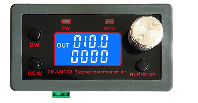
Connect the controller to a 24VDC source and turn the power on.
The display should show initial operaional settings.
Press and hold the control knob until the unit goes into the setup mode.
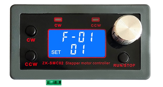
turn the knob clockwise until F03 is displayed.
The bottom line will show the default 010.0
Pres the control knob again to enter the bottom line edit mode.
The decimal value will be flashing.
The decimal value can be changed by rotating the control knob, but leave it at zero.
Press the knob again and the least significant digit will be flashing. Change it to 9.
Press again and change the next digit to 2.
Press again and change the first digit to 3.
The lower display should be reading 329.0 with number 3 flashing.
Do the extended press to get out of the setup mode.
Now 329.0 should be displayed on the top line and 0000 on the bottom line.
That sets the stepper RMP.
Now we have to set the running mode for continuous operation.
Do the extended press again to get into the setup mode.
F01 will be displayed on the top line and P01 on the bottom line.
Press the control knob and the bottom line should be flashing.
Change the bottom to P03 by rotating the control knob.
Do the extended press to get out of setup.
Quick Test
Press the CW button - the motor should run clockwise and the film cam should rotate at 3 RPM.
Press the stop button. The motor should stop.
Note: If the motor rotation is reversed then reverse the green and black wire connections.
Another Note: The reverse speed is set to 10 rpm which is slow. If planning to use the reverse operation then the reverse speed is set by changing the F05 field
by using similar procedure as listed above.
The camera used should be capable of caustom frame rates.
Sony A7iii supports custom rates but it is quite expensive.
An alternative is to obtain the T3i body and add the macro lens.
The stock camera does not support the custom frame rates but there is a custom software available that enables
custom frame rates and raw video.
Listed below are the instrustions on how to install Magic Lantern and set it up for FPS override, but before that here is a quick overview:
Download the build to your PC and unzip it.
Format the SD card by the camera itself.
Make sure your battery is fully charged. That is very important. You can ruin the camera if you do not follow these instructions carefully.
Install the SD card into the camera and power it up.
BTW - going forward any time you open the SD card cover, do not remove the SD card immediately, wait for the red led to stop flashing.
Set the camera to Manual mode
Press the MENU button
Go to the second last screen and press the Firmware button.
Double check the Magic Lantern instructions
https://builds.magiclantern.fm/600D-102.html
Do the update
Recycle power and you are ready to go.
Refer to https://magiclantern.fm/
for more details.
Specifically refer to this page for the T3i:
https://builds.magiclantern.fm/600D-102.html
For setting up the camera refer to:
https://www.youtube.com/watch?v=NYGseJ7Sofk
https://www.youtube.com/watch?v=RvZHmOgzm2Q&t=6s
Thsese two videos give you a pretty good idea on how to set the 3 FPS but there are some devil details missing.
Will try to cover those in here.
Set the camera to Movie mode.
Turn the camera on and turn on live preview.
This will start the Magic Lantern software.
Then press the delete button.
The settings screen will pop up.
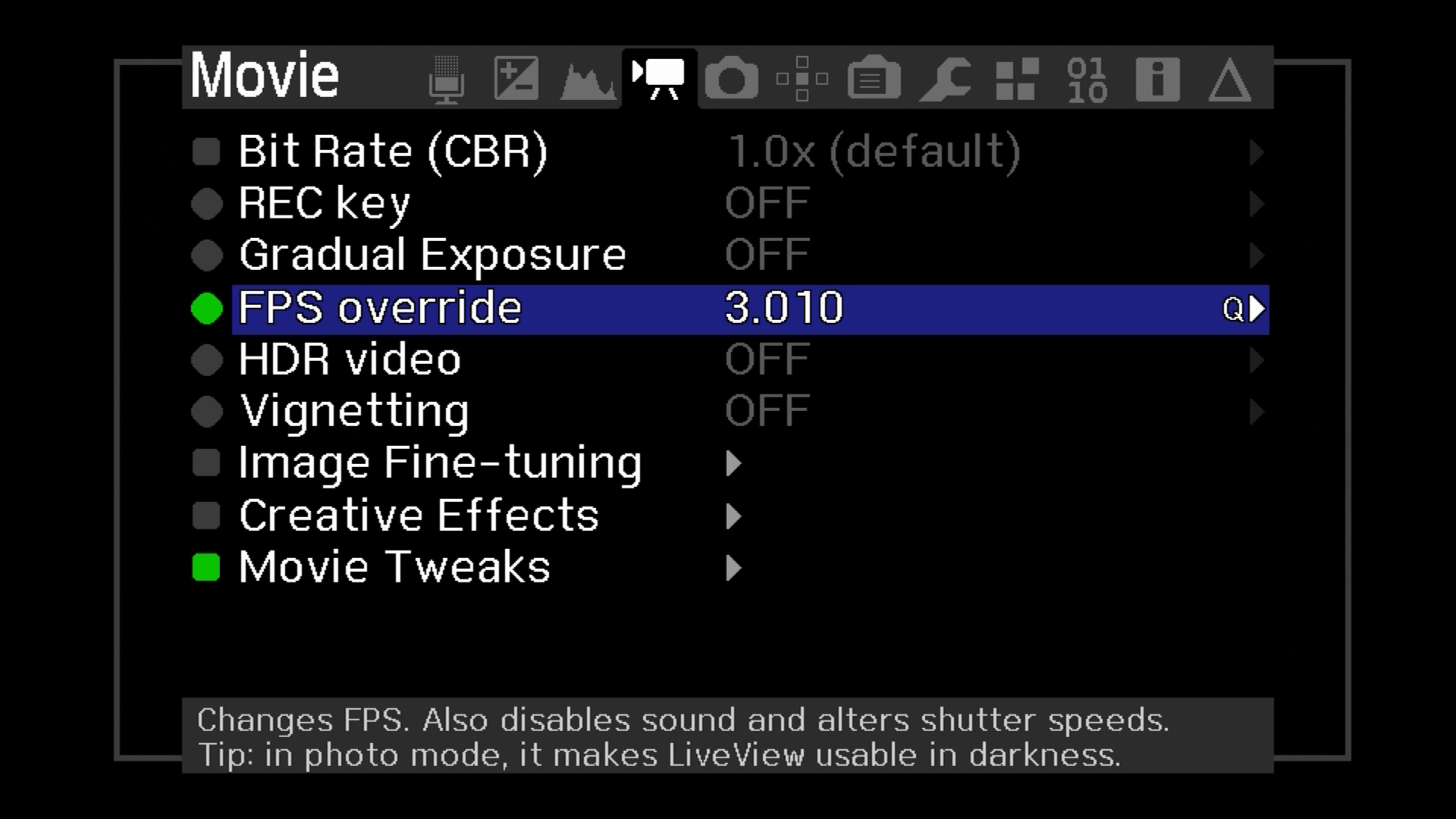
Go to the Movie screen:

Select FPS OVerride. Press enter to turn it on.

Then press the Q button on the T3i. Other camera types will have a similar button.
The FPS Override screen will pop up.

Hit the Q button.
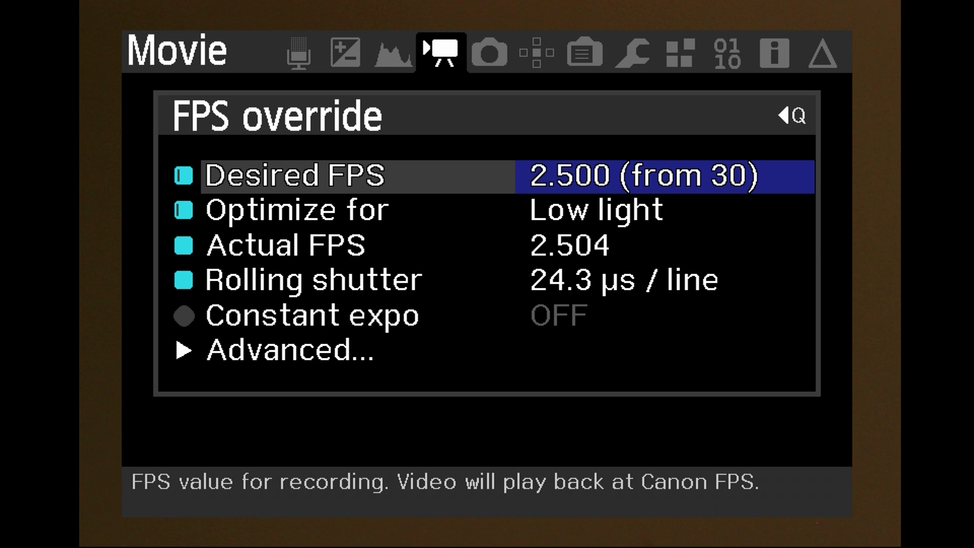
Position highlight over desire FPS and hit Enter. Set desired FPS to 3 by using the left and right keys.
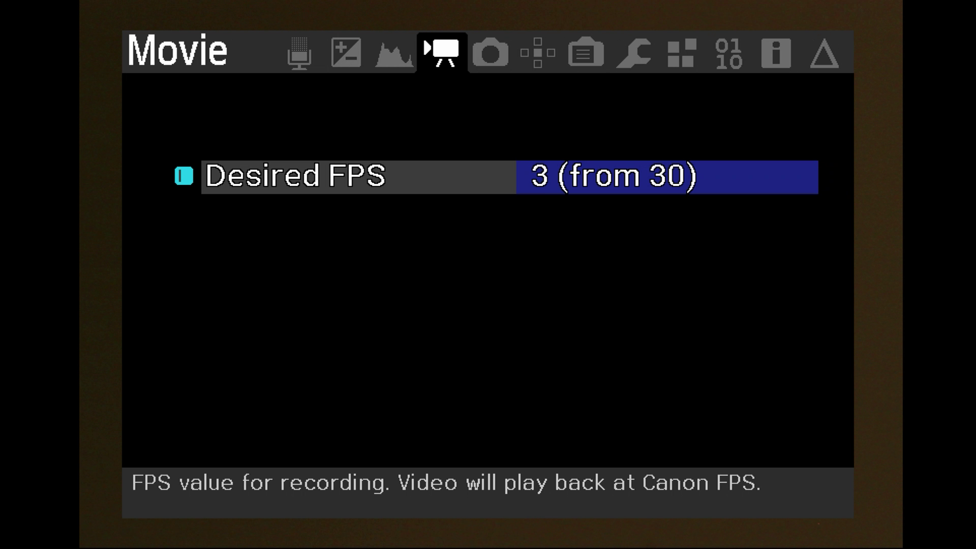
Press enter again to go bach to the FPS Override screen. Select the "Optimize for" entry and hit Enter.

Select High FPS
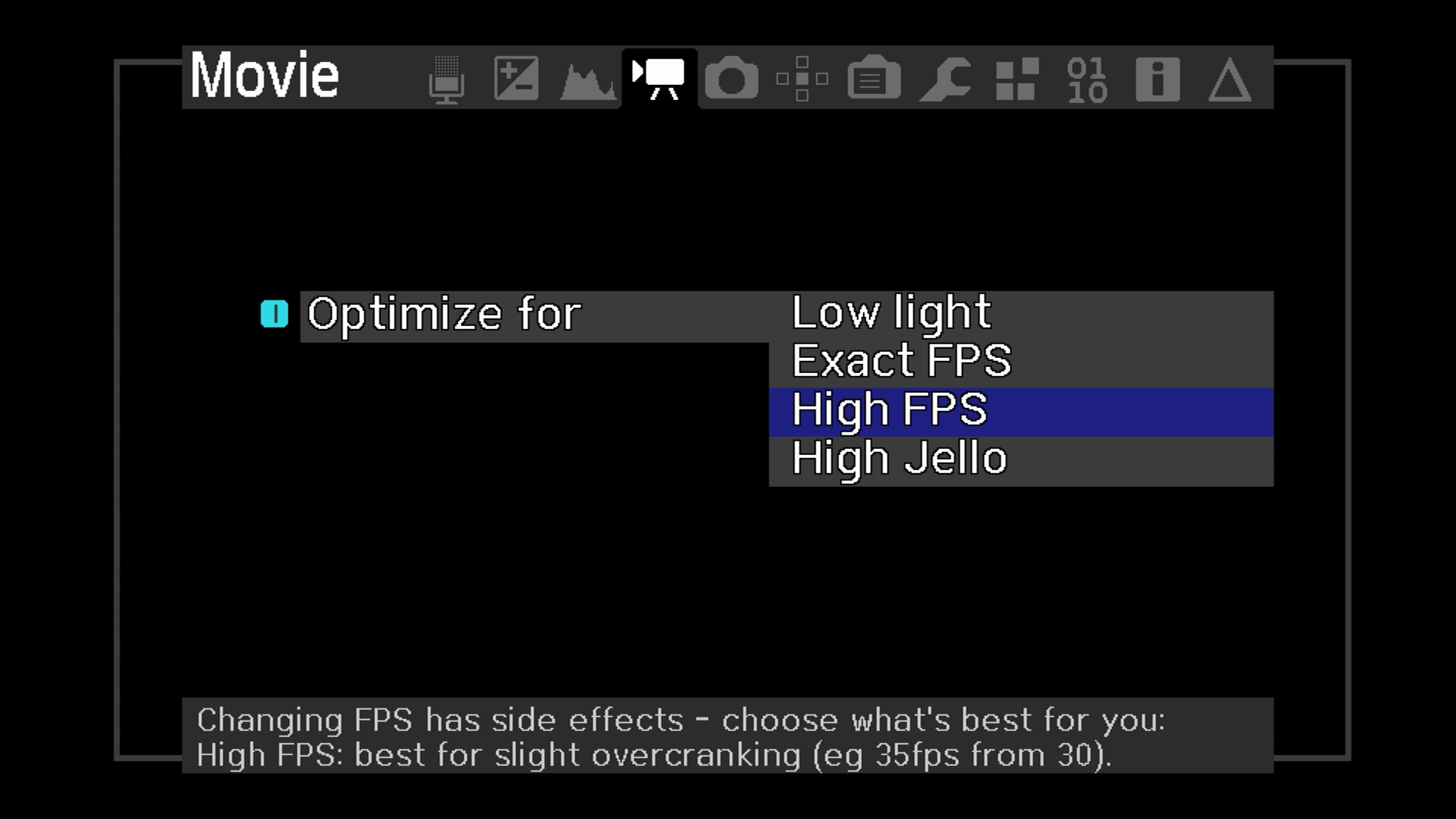
After selecting High FPS the camera will go back to the FPS override screen.

Select Advanced Mode.
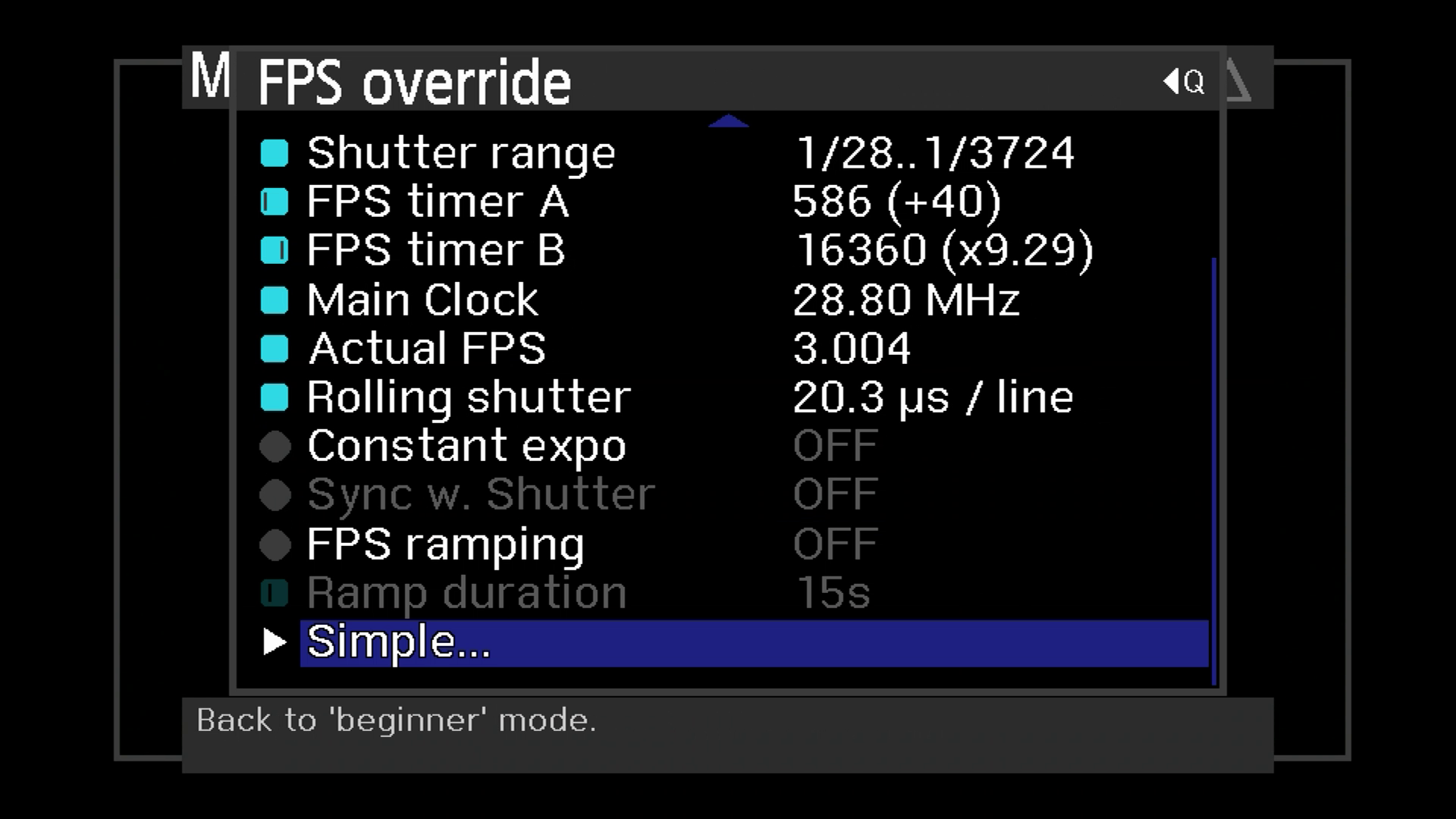
Select Timer B. Leave it as is for now but remebmer how you got to this point becase you will need it later
for sync procedure.

Go back to the FPS Override screen.
The shutter speed can be changed on the Expo screen.
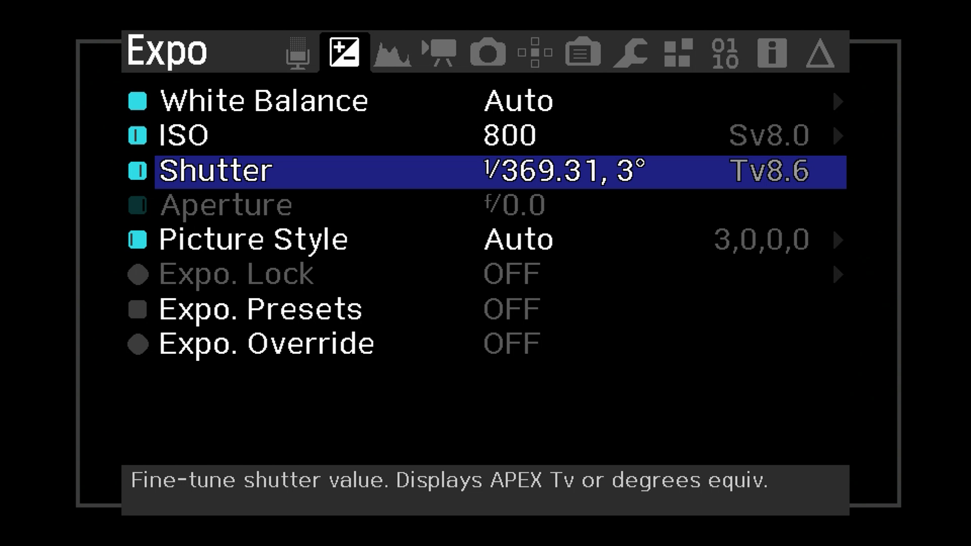
The shutter rspeed can also be changed while scanning the film by using the main dial. Check the manual fo main dial location (tp of the cam).
The light should be bright enough so that the shutter speed is 1/300 or faster. If the shutter is too slow than some image degradation can happen.
It is to be noted that even at this fast shutter setting, due to low FPS you could experience some jello effect. The jello effect exhibits itself as a
the video shrinking and expanding as jello and can be very annoying. The cause is the rolling shutter which stores one image line at a time. At slow scan
there is a shift in the top of the image as compared to the bottom of the image i.e. by the time the scan gets to the bottom the scene has changed somewhat.
But on a positive note, the postprocessing done in DaVinci Resolve almost completely eliminates this degradation.
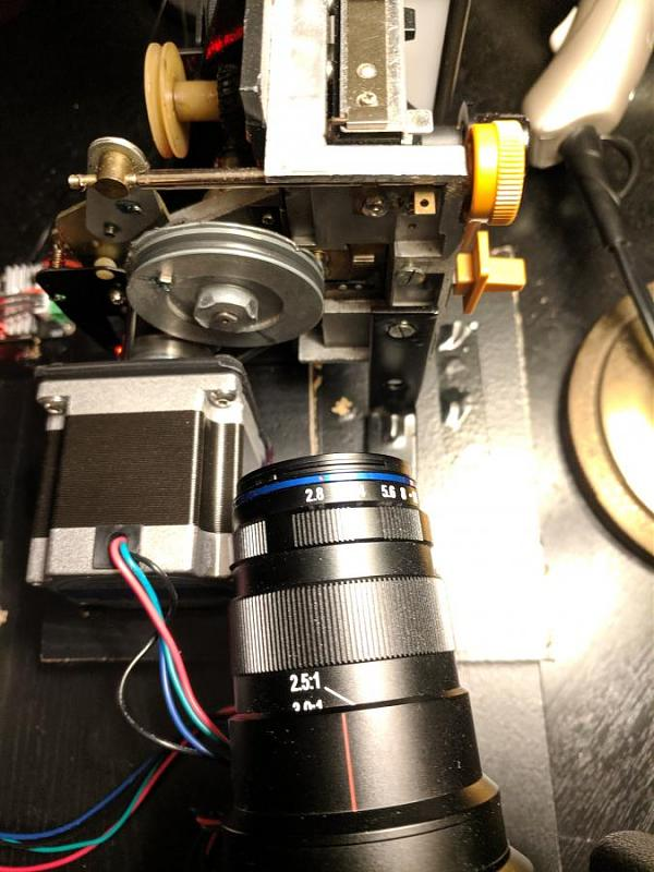
There are many out there that will do the job.
Venus Laowa is a pretty good pick. It has more than enough magnification and good image quality and it is reasonably priced.
https://www.venuslens.net/product/laowa-25mm-f-2-8-2-5-5x-ultra-macro-2/
Back it off and turn it away from the gate and point it to the cam (pulley). Adjust the speed control on the controller until the cam appears stationary. Actually it will jump up and down and possibly drift slowly. If the drift cannot be stopped by the speed control, then adjust the Magic Lantern Timer B to minimize the drift. Once done, refocus the camera back onto the gate. With this procedure I can run for several thousand frames without sync issues. It should be noted that the transport should be in good condition ensuring constant speed. It still may be possible that the drift catches up with you depending on the initial condition. In that case just run one step up for a few minutes if the drift is from the top, or one step down if the drift if coming from the bottom. Then switch back to the original speed. After that you can run for several thousand frames without sync issues
Load the film.
Plug in the 24V and 12V external power sources. 12V is for the takeup and 24 is for the controller.
Make sure that they are not reversed which can result in the takeup motor damage.
Turn the light on.
Connect the camera HDMI port to a monitor.
Turn the camera on and press the live view button. This will start Magic Lantern.
Press Live View again to start recording.
Press the CW button on the controller.
Once done with the recording, stop the camera by pressing the live view again abd stop the controller by pressing the stop button.
Remove the SD card and copy the MLV (Magic Lantern Video) to a PC.
Download the MLV app from:
https://mlv.app/
Install the app.
Open it up.
Drag the video into the session window as shown:
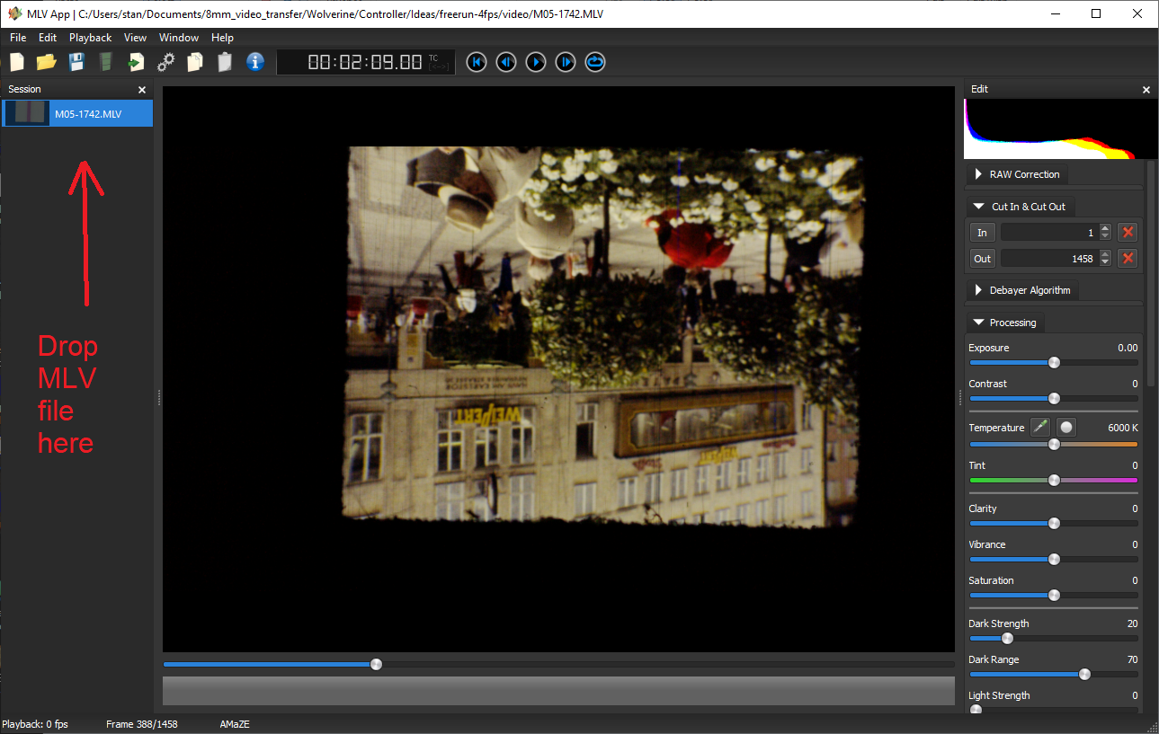
Expand the transformation entry on the right hand side and turn the Upside down control on.

Review the video to see if any sections have to be retaken. This app has pretty limited video edit capabilities
but it has lots of export formats suitable for popular video editors.
Open up export settings from File pulldown:

Select DNG uncompressed format if exporting to Resolve.
The DBG images take up lots of space but in return contain the raw information that can be utilied in DaVinci Resolve.
Export the video by using File->SaveVideo into the directory of your choice.
Close the mlvApp.
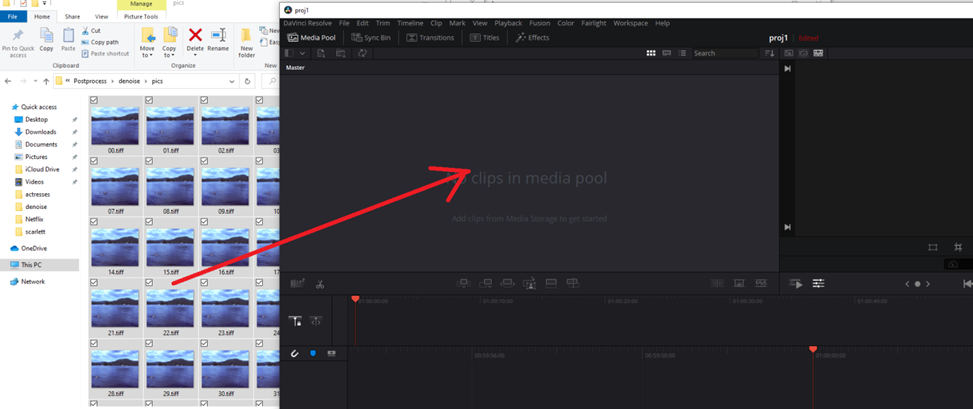
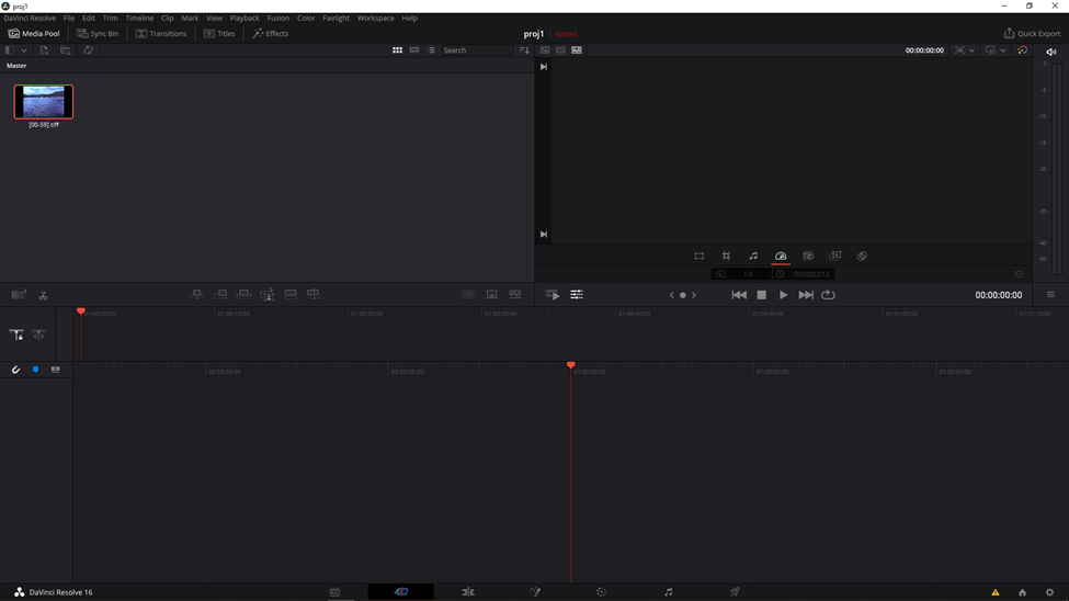
Open up Davinci Resolve and drag the DNG images into it.
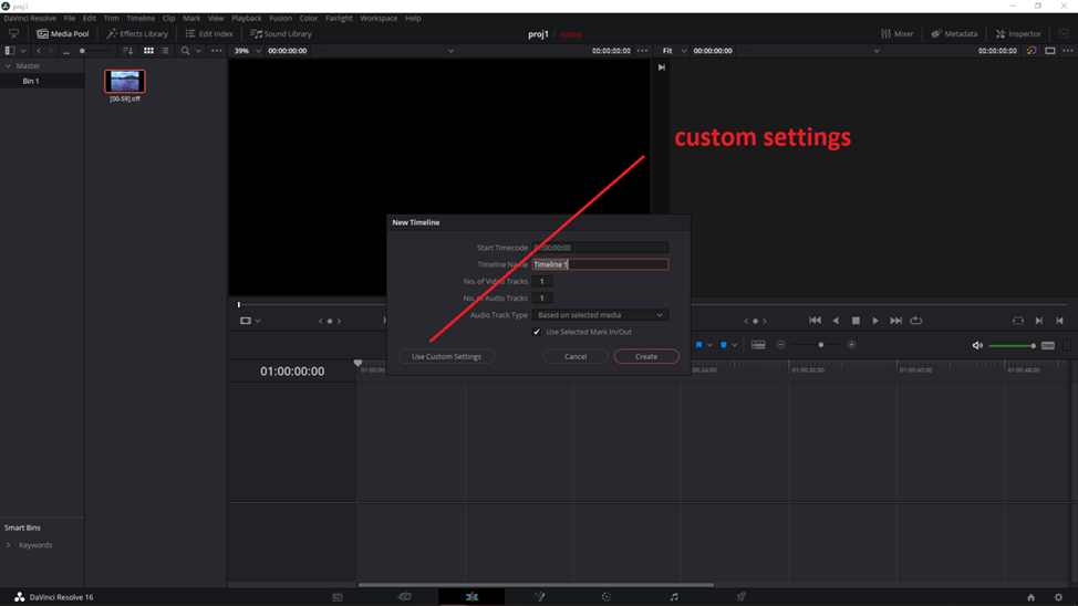
Right click on the clip and create the new timeline:

Click on Custom Settings and change the frame rate to what you need.
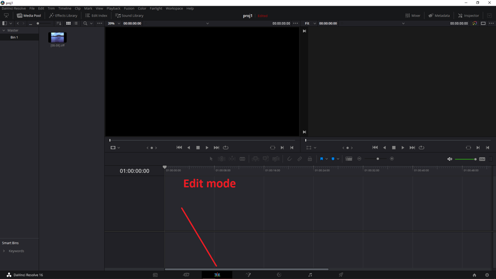
Switch to Edit Mode:
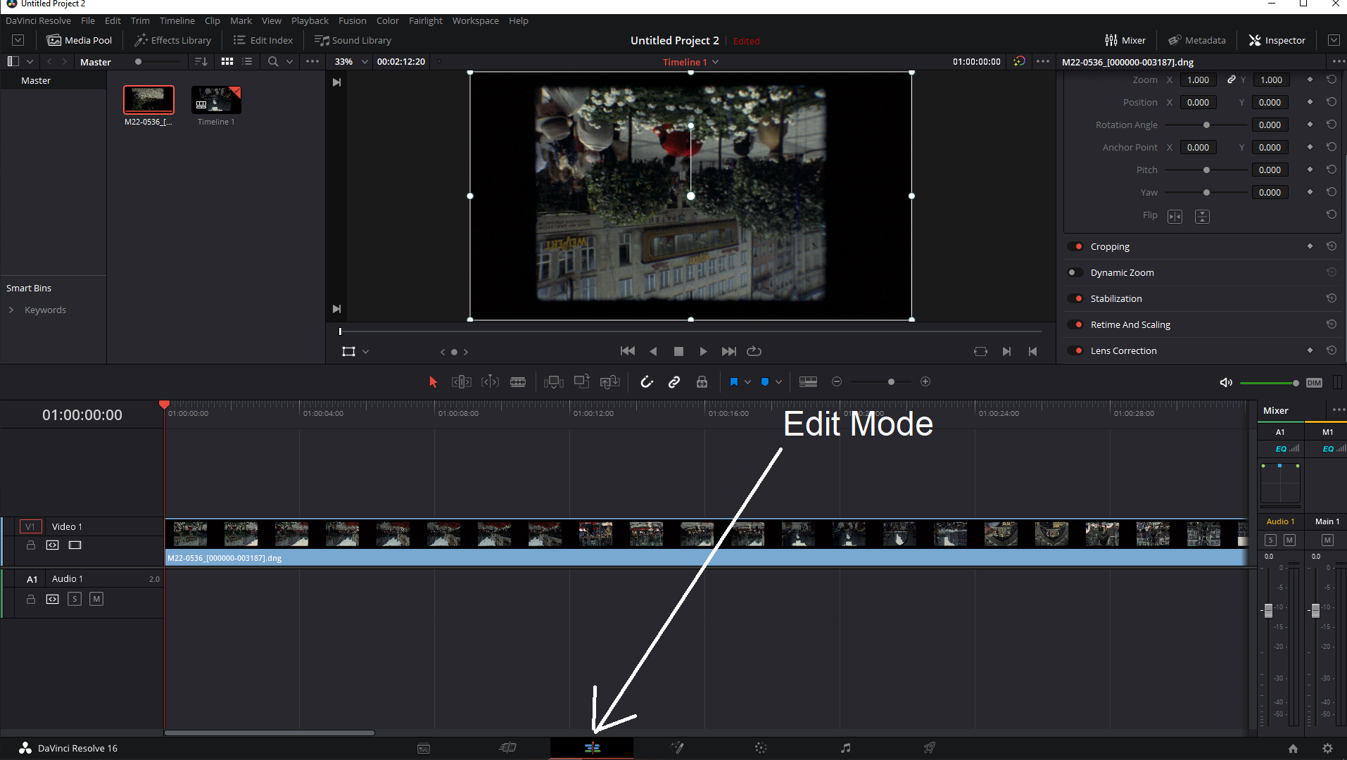
In the transform area on the right hand side, rotate the video by 180 degrees.

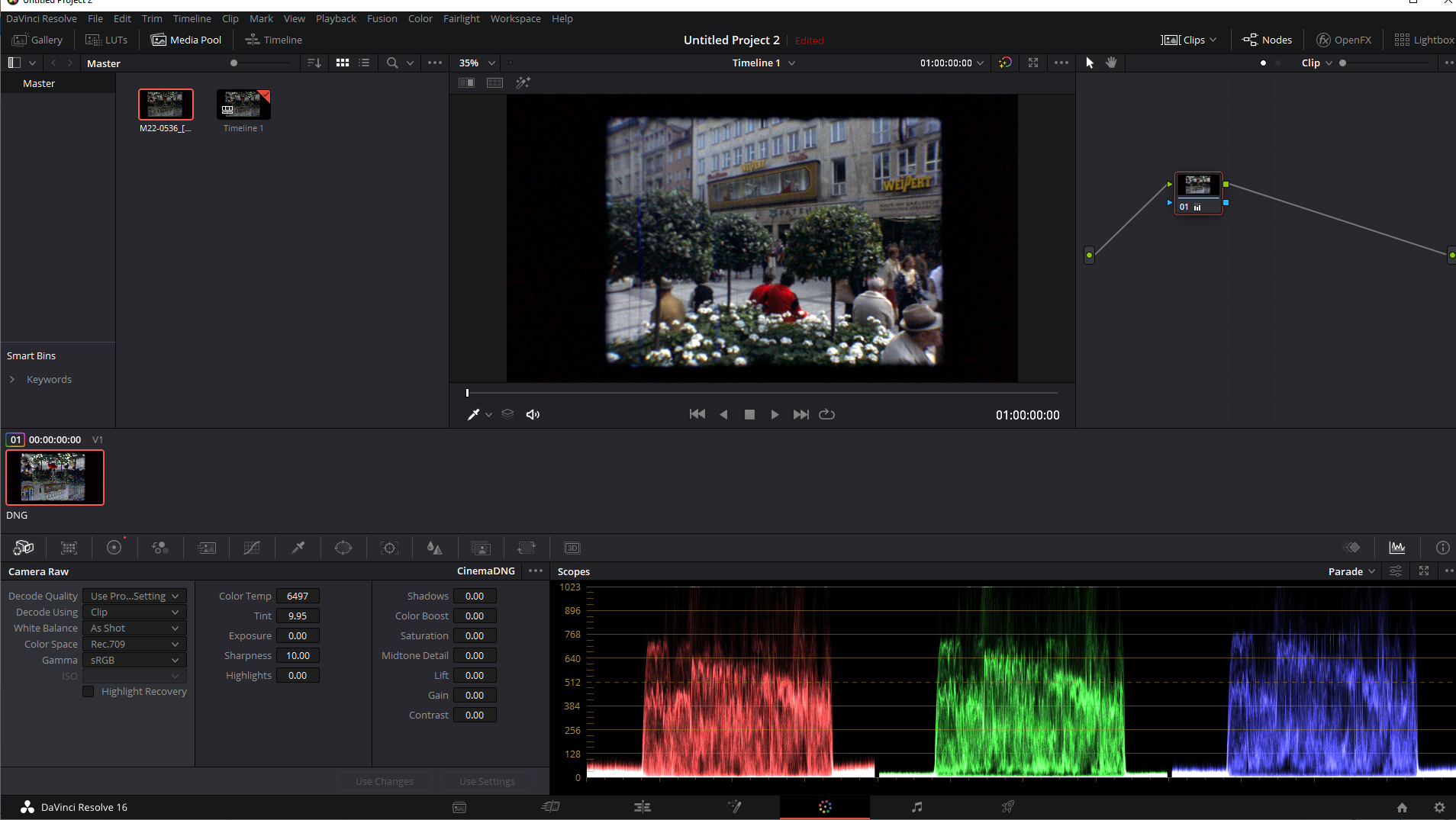
Switch to color edit mode. Select Camera Raw and Decode using Clip as shown:
Adjust exposure as shown:
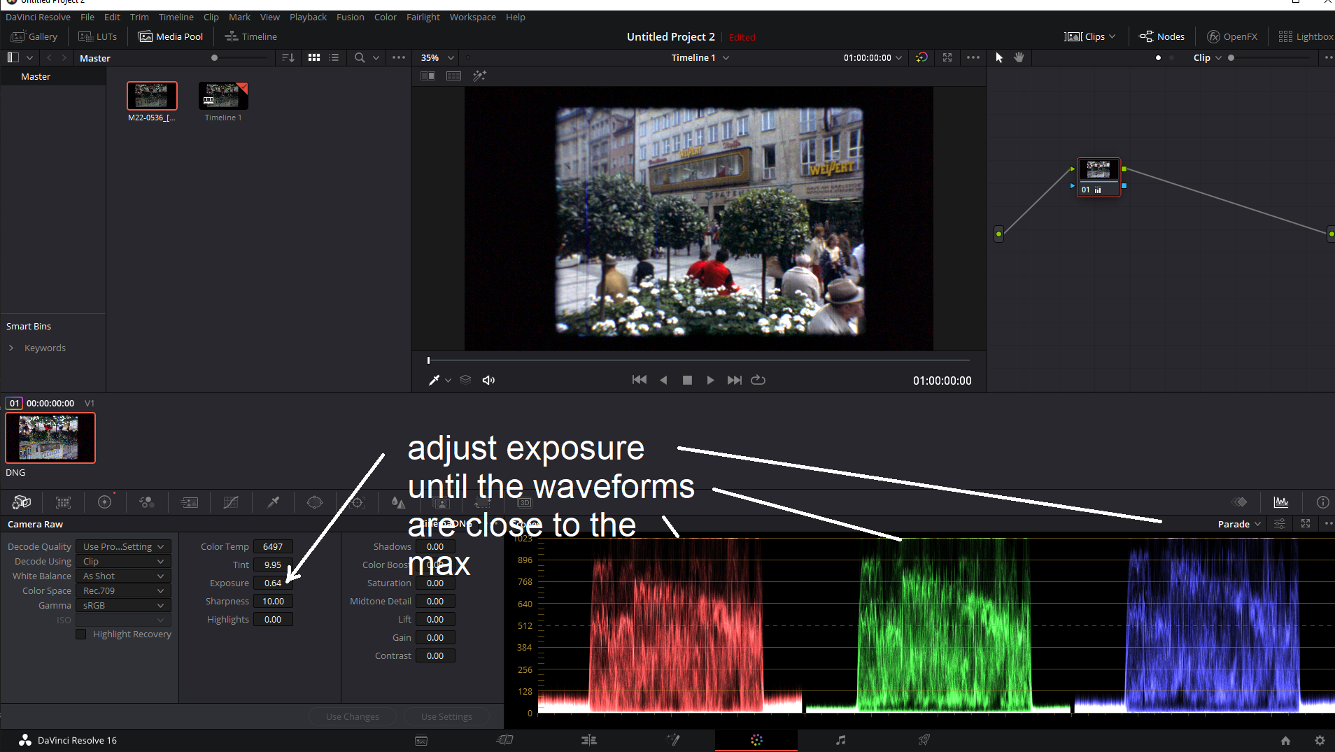
If the video shows a jello effect then this would have need adjustment.
Go back to the edit mode:
In the transform area on the right hand side scroll down to Stabilization.
Set mode to Perspective.
Turn on zoom and then adjust stabilization parameters as needed. It will be a trial and error process. Too little and the
video will be wavey and too much will cause severe clipping and loss of resolution.
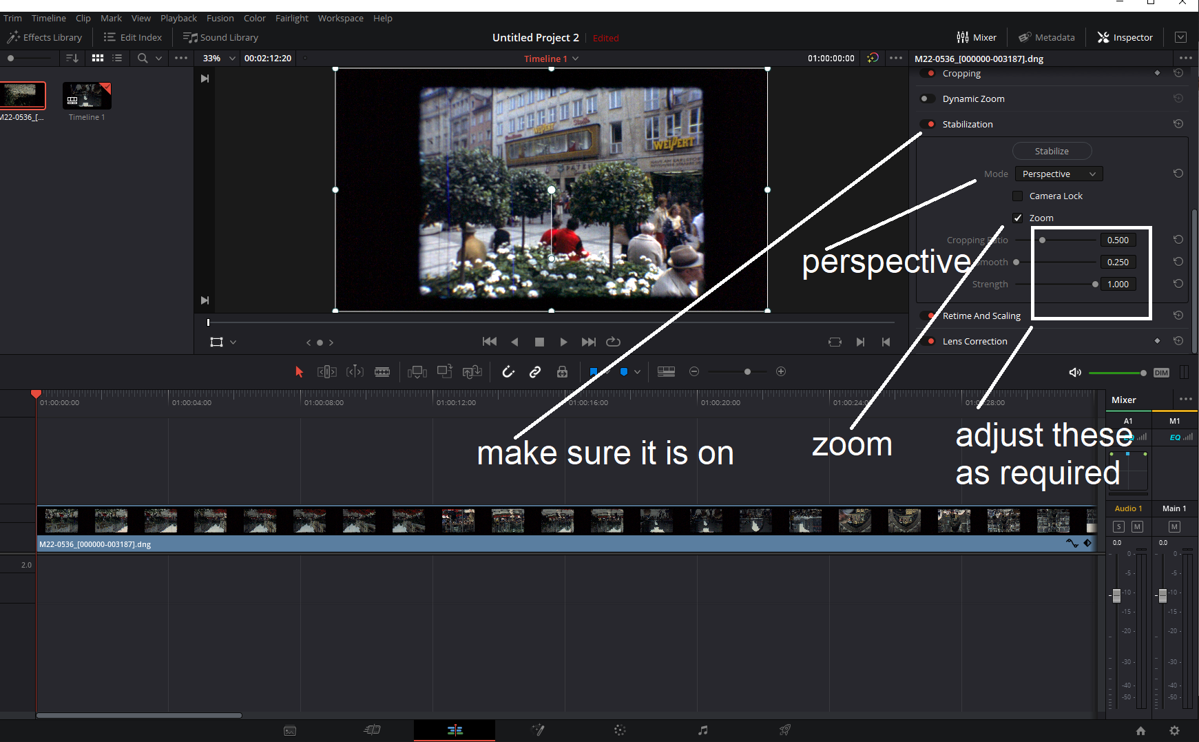
Click on the stabilize button to run stabilization. It may take a while.
https://www.youtube.com/watch?v=u6UWJCQB7n0
If the video has noticable jello effect then apply the Resolve stabilizer as shown the video below.
https://www.youtube.com/watch?v=73zwjGcbhP4
Save the VirtualDub2 video as a sequence of tiff images first.
Select all images and drag them into the media window of DR (DaVinci Resolve).
You will get the images shown as a clip in the media window.
Right click on the clip, select the click attributes and set the frame rate if necessary
but you can leave it as is since the frame rate change can be done later.
Right click on the clip and create the timeline from it.
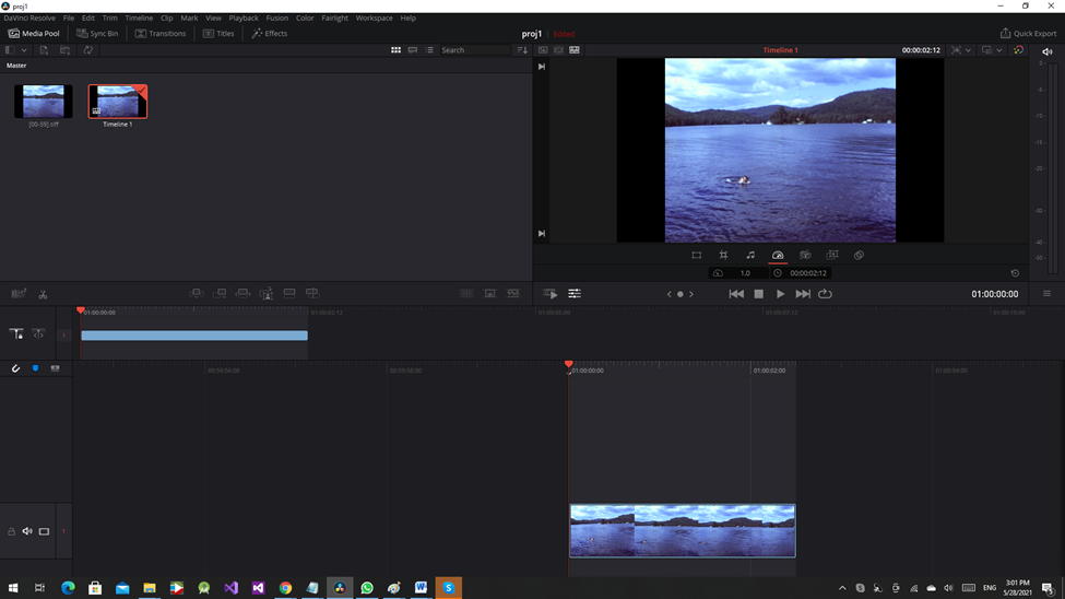
Switch to Edit Mode.

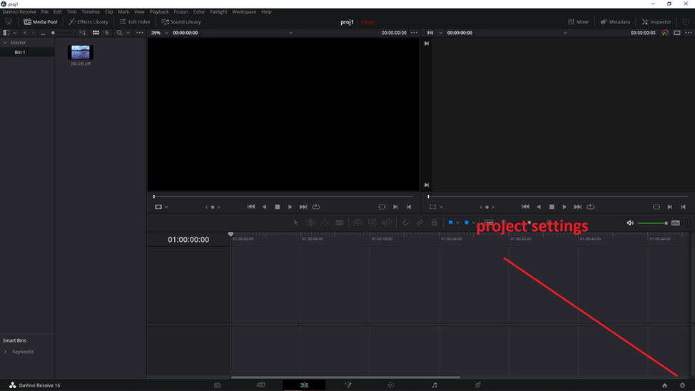
Click on project settings

Scroll the settings all the way down and change the retime process to optical flow (more info available here
htps://www.youtube.com/watch?v=m5cO3ZTfSr4 ).
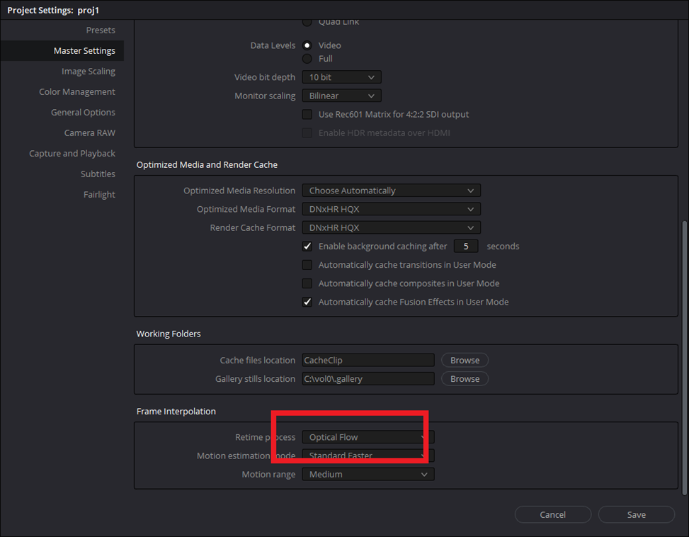
Save the settings.
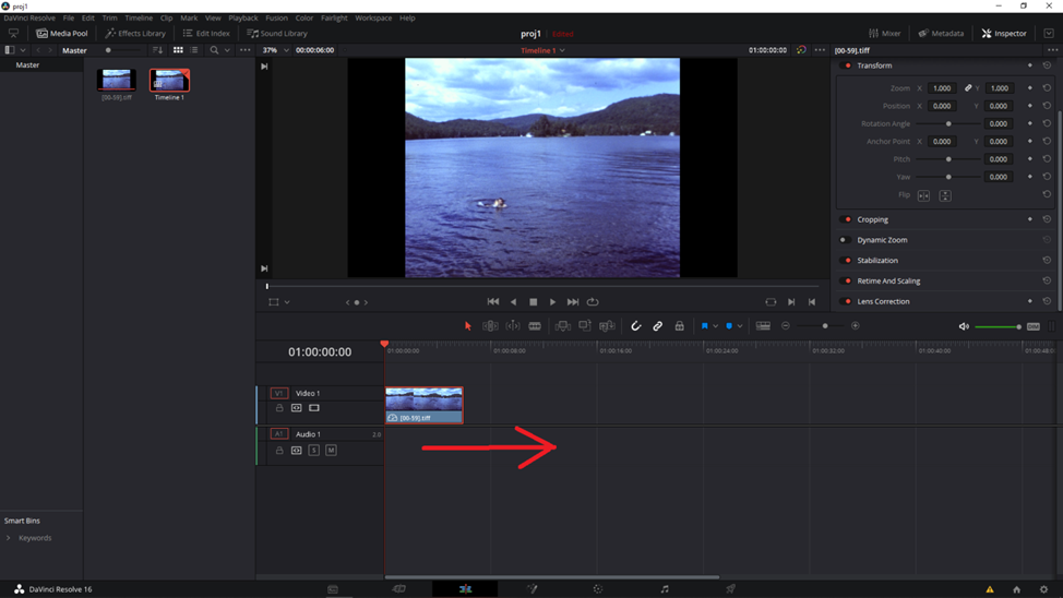
Now, right click on the clip and change the speed to whatever FPS needed.

Change the FPS to whatever required.

Make sure that Ripple sequence is checked off. If not the clip duration will not change and the clip will be truncated.
Click on the change button. Note the clip duration change in the timeline window.
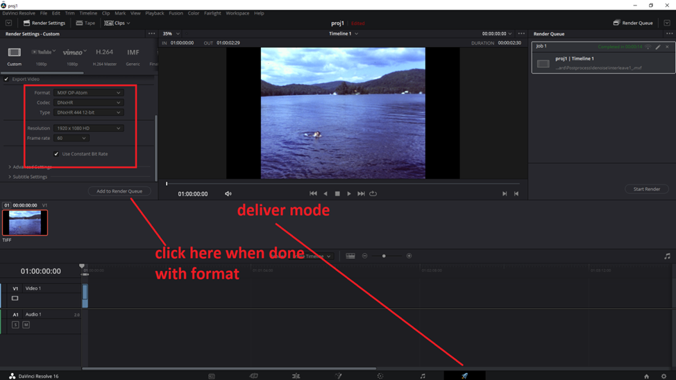
Once done, complete other changes as necessary and then export the video by switching to deliver mode.

Change the video format to whatever you like.
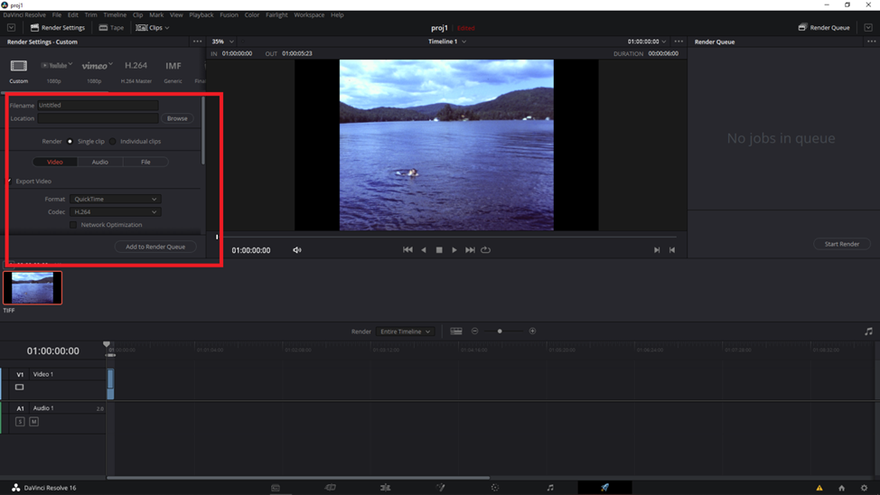
Add to render queue

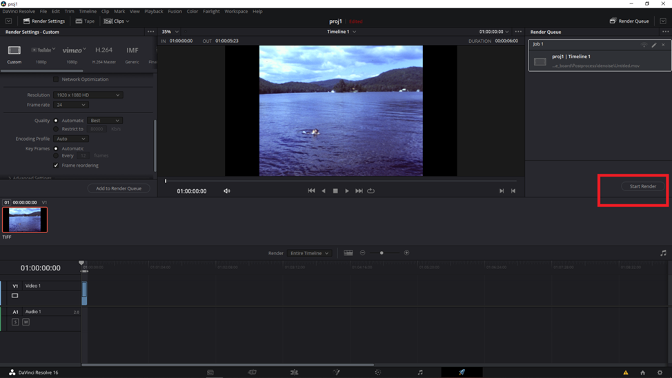
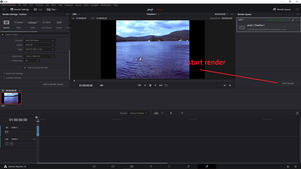
And then start render.
The above instructions were for interpolated frames that result in smooth slow motion speed.
In many cases however we want to interpolate the frames but want to maintain the original speed.
In order to do that just follow the above instructions but do the following changes.
- Make sure your project settings are set to optical flow for retiming.
- Before creating the timeline set the clip attributes FPS to 60 FPS.
- Create new timeline
- Using the above procedure change timeline speed to 24 FPS or whatever final speed you need
The rest is the same as the above procedure.
Here are the details.
Project settings optical flow selection.

Drag the images into the media window. Make sure all images are selected.

Switch to edit mode if not already there.
Right click on the images file in the media window and select clip attributes.
Set clip FPS to 60 or whatever interpolation rate you prefer.
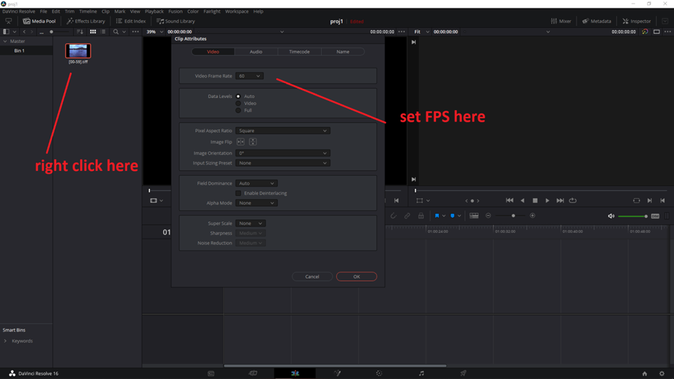
Click on OK.
Right click on the clip again and create the timeline. The timeline create window pops up.
Click on custom settings.
It is to be noted that in version 17.2 of DaVinci the timeline popup window is a bit different.
It does not have custom settings but it has a button to use the Poject Settings.
Make sure that button is not checked off.

Select Format tab and set the desired interpolation FPS.

The new timeline will show up in the timeline window.
Right click on the timeline in the timeline window and select Change clip speed.
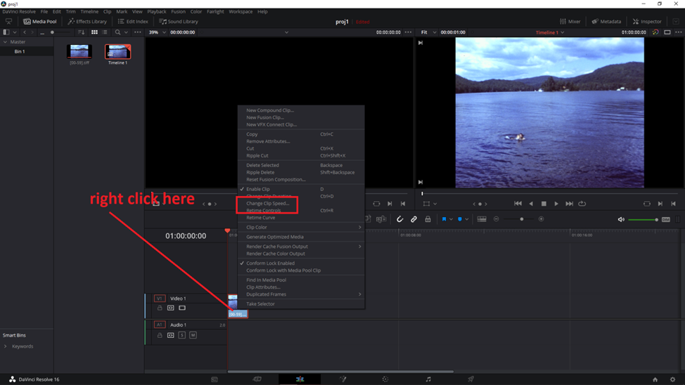
Change clip speed back to normal speed i.e. 24 or 18 FPS or whatever the original speed was.
You can also go lower if slow motion is preferred. Make sure Ripple sequence is checked off.
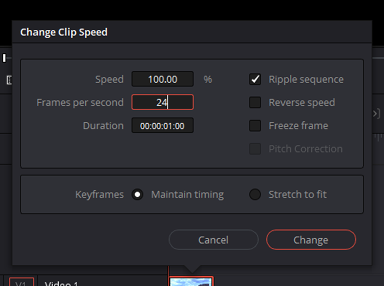
Note the clip stretching out after the speed change.
If t does not then make sure that Ripple sequence is checked off.
At that is basically it.
You can test run the clip to make sure that additional frames got added by stepping through the video (left, right arrows).
The next step is to render and save the video.
Switch to Deliver Mode.

Select proper video format and add to render queue.
Start rendering.
And that completes the procedure.