Parallel EEPROM Programmer for 28C64B and 28C256 featuring:
- GUI-based front-end written in Python
- Possibility to access the programmer via a serial monitor
- Hardware SPI with 8 Mbps to control address bus via shift registers
- Hardware UART with 1 Mbps for data transfer to/from PC via USB 2.0
- Utilizing the fast page write mode of the EEPROM
- Binary data transmission
- Project Video (YouTube): https://youtu.be/FkSXgdC_ToQ
- Design Files (EasyEDA): https://easyeda.com/wagiminator/y-atmega-eeprom-programmer
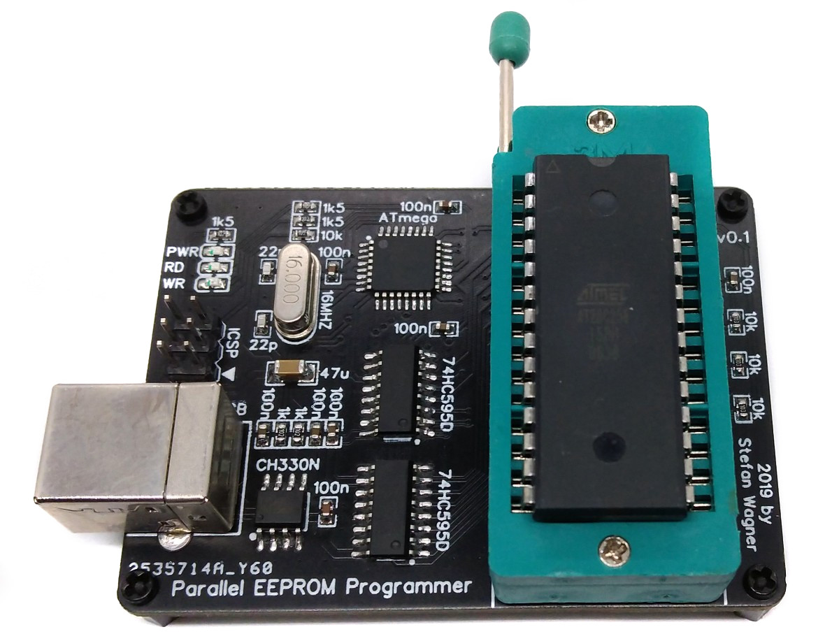
The heart of the EEPROM programmer is an ATmega8 microcontroller. The address bus of the EEPROM (up to 15 bit) is controlled via two daisy-chained 74HC595 shift registers using hardware SPI @ 8 Mbps. The data bus is controlled directly via the pins of the ATmega. Address and data bus are simultaneously driven to achieve the maximum data transfer rate. The data connection to the PC runs via the hardware UART interface of the ATmega transfering the data in binary format with up to 1 Mbps. A CH330N (or CH340N) converts the serial data for USB 2.0.
This EEPROM is a high-performance electrically erasable and programmable read-only memory. The device offers access times to 150 ns with power dissipation of just 440 mW. When the device is deselected, the CMOS standby current is less than 200 μA. The EEPROM is accessed like a Static RAM for the read or write cycle without the need for external components. The device contains a 64-byte page register to allow writing of up to 64 bytes simultaneously. The end of a write cycle can be detected by data polling. Once the end of a write cycle has been detected a new access for a read or write can begin. An optional software data protection mechanism is available to guard against inadvertent writes. The EEPROM is ideally suited to replace (E)EPROMs in old 8-bit computers.

The EEPROM is accessed like a Static RAM. When !CE and !OE are low and !WE is high, the data stored at the memory location determined by the address pins is asserted on the outputs. The outputs are put in the high impedance state when either !CE or !OE is high.
A low pulse on the !WE or !CE input with !CE or !WE low (respectively) and !OE high initiates a write cycle. The address is latched on the falling edge of !CE or !WE, whichever occurs last. The data is latched by the first rising edge of !CE or !WE. Once a byte write has been started it will automatically time itself to completion. The page write operation allows 1 to 64 bytes of data to be written into the device during a single internal programming period. A page write operation is initiated in the same manner as a byte write; the first byte written can then be followed by 1 to 63 additional bytes. Each successive byte must be written within 150 μs of the previous byte. All bytes during a page write operation must reside on the same page as defined by the state of the A6 - A14 inputs. For each WE high to low transition during the page write operation, A6 - A14 must be the same. The A0 to A5 inputs are used to specify which bytes within the page are to be written. The bytes may be loaded in any order and may be altered within the same load period. Only bytes which are specified for writing will be written; unnecessary cycling of other bytes within the page does not occur.
The EEPROM features DATA Polling to indicate the end of a write cycle. During a byte or page write cycle an attempted read of the last byte written will result in the complement of the written data to be presented on I/O7. Once the write cycle has been completed, true data is valid on all outputs, and the next write cycle may begin. DATA Polling may begin at anytime during the write cycle. In addition to DATA Polling the EEPROM provides another method for determining the end of a write cycle. During the write operation, successive attempts to read data from the device will result in I/O6 toggling between one and zero. Once the write has completed, I/O6 will stop toggling and valid data will be read. Reading the toggle bit may begin at any time during the write cycle.
On the microcontroller side, data is received via UART and written to the EEPROM according to the data sheet or vice versa. The programmer is controlled with simple commands, which are also sent via the serial interface:
| Command | Function |
|---|---|
| i | Print "EEPROM Programmer" (for identification) |
| v | Print firmware version |
| a 0100 | Set address bus to 0100 (hex) (for test purposes) |
| d 0000 7fff | Print hex dump of memory addresses 0000-7fff (hex) |
| f 1000 1fff ff | Fill memory (1000-1fff) with value ff (hex) |
| r 0000 3fff | Read memory addresses 0000-3fff (hex) and send as binary data |
| p 0100 013f | Page write binary data to memory page 0100-013f (bytes must follow) |
| l | Lock EEPROM (enable write protection) |
| u | Unlock EEPROM (disable write protection) |
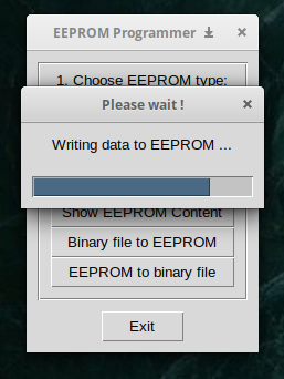
Any serial monitor (set BAUD rate to 1000000) can be used for control from the PC. However, in order to use the full capabilities, it is recommended to use the attached Python scripts. The script "eepromgui.py" offers a simple graphical user interface and functions for reading and writing binary files as well as for displaying the EEPROM content. The scripts have only been tested on Linux, but should work on all operating systems.

- Make sure you have installed MiniCore.
- Go to Tools -> Board -> MiniCore and select ATmega8.
- Go to Tools and choose the following board options:
- Clock: External 16 MHz
- BOD: BOD 4.0V
- Compiler LTO: LTO enabled
- Bootloader: No bootloader
- Leave the rest at the default settings
- Connect your programmer to your PC and to the ICSP header of the device.
- Go to Tools -> Programmer and select your ISP programmer (e.g. USBasp).
- Go to Tools -> Burn Bootloader to burn the fuses.
- Open EEPROM_Programmer sketch and click Upload.
- Make sure you have installed avrdude.
- Connect your programmer to your PC and to the ICSP header of the device.
- Open a terminal.
- Navigate to the folder with the hex-file.
- Execute the following command (if necessary replace "usbasp" with the programmer you use):
avrdude -c usbasp -p m8 -U lfuse:w:0x3f:m -U hfuse:w:0xd1:m -U flash:w:eeprom_programmer_m8.hex
- Make sure you have installed avr-gcc toolchain and avrdude.
- Connect your programmer to your PC and to the ICSP header of the device.
- Open a terminal.
- Navigate to the folder with the makefile and the Arduino sketch.
- Run
PROGRMR=usbasp make installto compile, burn the fuses and upload the firmware (change PROGRMR accordingly).
Python needs to be installed on your PC in order to use the software. Most Linux distributions already include this. Windows users can follow these instructions. In addition PySerial and Tkinter (8.6 or newer) must be installed. However, these are already included in most Python installations.
Windows users may also need to install a driver for the CH330N/CH340N USB to serial adapter. This is not necessary for Linux or Mac users.
- Connect the EEPROM Programmer via USB to your PC.
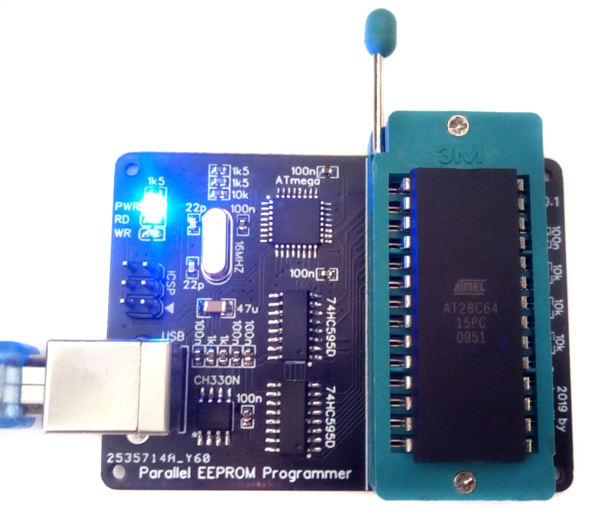
- Insert your EEPROM into the ZIF socket with pin1 facing to the handle of the socket.
- Run the eepromgui.py application.

This work is licensed under Creative Commons Attribution-ShareAlike 3.0 Unported License. (http://creativecommons.org/licenses/by-sa/3.0/)