120ChannelDeviceConnector
Table of Contents generated with DocToc

- Hardware designs
- If you're soldering this board yourself, check out this page for some helpful tips.
All parts are described in the 120-channel device connector repository, which also contains `stl` files for all 3D printed parts and `svg` files for laser cut parts. The collection of files can be downloaded by clicking on the latest "snapshot" link.
| Quantity | Description | Image |
|---|---|---|
| 1 | Base plate |  |
| 1 | Top plate |  |
| 2 | Hinge pins |  |
| 1 | Right clasp |  |
| 1 | Left clasp |  |
| 1 | Right camera arm |  |
| 1 | Left camera arm |  |
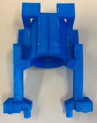
| 1 | Camera holder |  |
These parts should be cut from 3mm clear acrylic.
| Quantity | Description | Image |
|---|---|---|
| 2 | Acrylic windows |  |
| Quantity | Description | Source |
|---|---|---|
| 4 | Machine screw (M3, .5mm pitch, 8mm) | McMaster-Carr |
| 4 | Machine screw (M3, .5mm pitch, 12mm) | McMaster-Carr |
| 2 | Machine screw (M3, .5mm pitch, 16mm) | McMaster-Carr |
| 12 | Thin hex nut (M3, .5mm pitch, 1.8mm height) | McMaster-Carr |
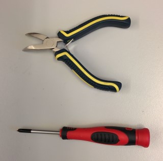
- Phillips #1 screwdriver
- Needle-nose pliers
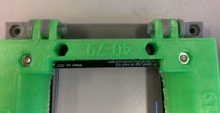
Fit the acrylic windows into the base plate. The cut outs should be facing out, which will allow you to perform fine adjustments of the device location if necessary (so that your contact pads align with the contact pads).

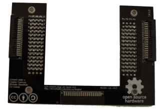
Using 4 M3 8mm machine screws and 4 M3 nuts, attach the pogo pin connector PCB to the top plate.

Attach the top plate to the base plate using 2 hinge pins. These should just snap in.
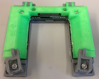
Attach the right and left clasps to the base plate through the innermost holes using 2 M3 16mm machine screws and 2 M3 nuts. The screws should come in from the bottom and the nuts should sit in a inset within each clasp. Because these nuts will tend to loosen over time, you can then add a second M3 nut to each screw, and tighten it down using the needle-nose pliers.
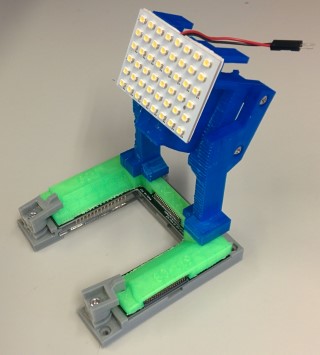
Using 4 M3 12mm machine screws and 4 M3 nuts, attach the camera arms to the camera holder. This camera attachment can be easily attached and/removed from the device connector.
For lighting, we use simple LED panels (e.g., available on ebay) attached to the front face of the camera holder and reflected off a piece of white paper attached to the camera holder using binder clips. This provides even lighting across the device and eliminates reflections and glare from overhead lighting.

If you can get LED panels that run off of 5 or 12V, you can power them from the power jacks available at the back of the !DropBot by making a custom cable assembly.