Skip to content
New issue

Have a question about this project? Sign up for a free GitHub account to open an issue and contact its maintainers and the community.

By clicking “Sign up for GitHub”, you agree to our terms of service and privacy statement. We’ll occasionally send you account related emails.

Already on GitHub? Sign in to your account

[feature] Include connector pinout diagrams #27

Open
formatc1702 opened this issue Jun 27, 2020 · 21 comments
Open

[feature] Include connector pinout diagrams #27

formatc1702 opened this issue Jun 27, 2020 · 21 comments

Comments

@formatc1702
Copy link
Collaborator

This would be a fantastic feature, but might be hard to implement.

Some questions

  • Load existing graphics or auto-generate (how?)?
  • One diagram per connector series/family/type, or one for every specific part?
  • From which side of connector? Cable side or mating side?
@X-Ryl669
Copy link

X-Ryl669 commented Jun 28, 2020

It looks like you need a way to import footprint from CAD software like Altium, Kicad, Horizon or LibrePCB. I think the current de-facto standard would be Kicad.
This project might help for parsing the footprint, but code need to be written to export to a format Graphviz supports.

@formatc1702 formatc1702 changed the title Include connector pinout diagrams [feature] Include connector pinout diagrams Jun 28, 2020
@seblovett
Copy link

This would be a great feature.
Rather than using a footprint (which would be odd as these would be the mating halves to the parts used here), could it be a path to an image? Datasheets usually have an image of pins on the connector (examples attached). This could be displayed next to the connector.
I used to crop these out when doing drawings.
Might get complex of where to put the image, especially in the more complex daisy chained wires.
fischer
jst

@formatc1702
Copy link
Collaborator Author

Official datasheet pictures would be best; however, this would mean maintaining a potentially huge library of connectors, which might be best suited to be a project of its own... and I am not sure about any copyright issues when using vendors' graphics...

The alternative would be generating "our" own graphics. I've even thought about defining them in 3D as parametric OpenSCAD files (e.g. adaptive pin count), and building a little script that renders them (edges only, no shading) in a set (isometric?) perspective and imports the resulting vector file.

The more I think about it, I really think this should be its own project... 🤔

@X-Ryl669
Copy link

What about adding a new key picture to the connector item to a .png or .svg and let the user decide if and what to use ?

@formatc1702
Copy link
Collaborator Author

That would be the easiest option, yes. I'll think about how to integrate this into the GraphViz output...

@seblovett
Copy link

Yes, definitely up to the user for adding the images. Maintaining a library is difficult to say the least!

@wulfenite
Copy link

I would also love this feature. Here's a screenshot of a diagram I modified post-hoc to show the connectors.
sample-wireviz-harness

I like the idea of user-definable PNG or SVG connector images placed on the outside of the tables (connecting them the way I have done above would probably be unnecessarily difficult).

@formatc1702 formatc1702 added this to the v0.3 milestone Jul 21, 2020
@kvid
Copy link
Collaborator

kvid commented Jul 29, 2020

This look can be implemented quite easily, supporting images for both connectors and cables:
demo01img
I can create a draft PR if this looks useful as a first implementation. Please send links to sample images we can legally use for free.

@wulfenite
Copy link

That seems like a great first start. Here's a sample diagram for a high-density D-Sub26 connector and for a 4-pin terminal block, unfortunately in different styles. The terminal block seems more useful for a demo.

It would be even better to have the option to link wires to specified locations on the connector, as in my wiring example above, but your suggestion certainly seems like a really good option for the much lower amount of work required. I would use the feature as you illustrated it!

@kvid
Copy link
Collaborator

kvid commented Jul 29, 2020

That seems like a great first start.

Thank's.

Here's a sample diagram for a high-density D-Sub26 connector and for a 4-pin terminal block, unfortunately in different styles. The terminal block seems more useful for a demo.

high-density D-Sub26 connector 4-pin terminal block
These images are good candidates, but I didn't find any description of legal usage at their web site.

There are a few alternatives at openclipart.org that I found via all-free-download.com, but additional links are welcome.

It would be even better to have the option to link wires to specified locations on the connector, as in my wiring example above, but your suggestion certainly seems like a really good option for the much lower amount of work required. I would use the feature as you illustrated it!

It should be possible to place an image between the wires and the connector pins, and to scale it to fill the height of the connector pins, but there are some more issues:

  • We might need both a left-side image and a right-side image.
  • Not all connector images are easy to adapt to obtain a nice result with this image location, e.g. the D-sub series like the DE-9F in my example diagram above and your first image candidate (seems like a DA-26F).

@formatc1702
Copy link
Collaborator Author

formatc1702 commented Jul 29, 2020

Let's not forget the earlier comment:

Yes, definitely up to the user for adding the images. Maintaining a library is difficult to say the least!

@kvid's demo image 3 comments up looks great and I am happy to include an image attribute for connectors and cables, but maintaing a connector library should be outside of the WireViz project scope.

If anybody wants to start a separate wireviz-images repo, knock yourselves out :)

@kvid
Copy link
Collaborator

kvid commented Jul 29, 2020

Let's not forget the earlier comment:

Yes, definitely up to the user for adding the images. Maintaining a library is difficult to say the least!

@kvid's demo image 3 comments up looks great, but maintaing a connector library should be outside of the WireViz project scope.

If anybody wants to start a separate wireviz-images repo, knock yourselves out :)

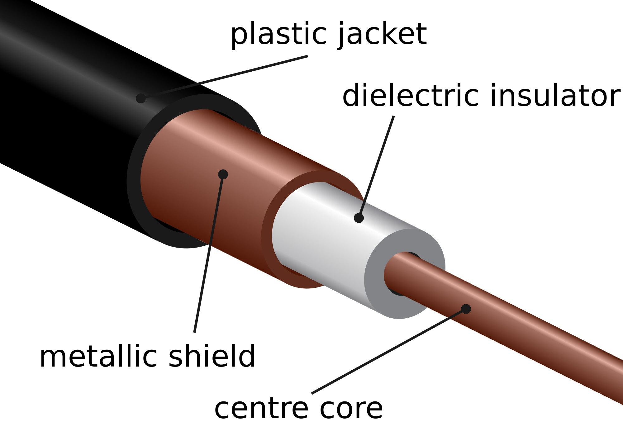
I'm sorry that my request for sample images is interpreted as a request to collect a library. That is not my intention at all. I fully agree with the comments about not maintaining a library (that's also why I added 👍 to them long ago).

However, I need a couple of nice looking images to demonstrate the feature, and want more suggestions to choose from. The DE-9F I used above is cropped from a larger image that might not be free to use for any purpose. A nice example for a cable image is also useful. I'm thinking about maybe something like these: coaxial cable, B/W coaxial cable, speaker cable, but they must look good after scaling down, and they must be free to use for any purpose.

Please suggest image candidates for an example harness we can include in the project.

@formatc1702
Copy link
Collaborator Author

formatc1702 commented Jul 30, 2020

One important thing that's missing from the sample images discussed so far:
⚠️ The important distinction whether one is looking at the connector from the mating side, or the opposite crimp insert / soldering side, which would flip the pin numbering.
I've seen both; this often varies across manufacturers, since there's no real standard. It's just a matter of whether they are thinking from the assembler's perspective, or the end user's.
This is especially critical for D-Sub connectors, which are symmetric, and look essentially the same from both sides.

Just something to keep in mind, not only for WireViz, but for life in general ;)

@kvid
Copy link
Collaborator

kvid commented Jul 30, 2020

One important thing that's missing from the sample images discussed so far:
⚠️ The important distinction whether one is looking at the connector from the mating side, or the opposite crimp insert / soldering side, which would flip the pin numbering.
I've seen both; this often varies across manufacturers, since there's no real standard. It's just a matter of whether they are thinking from the assembler's perspective, or the end user's.
This is especially critical for D-Sub connectors, which are symmetric, and look essentially the same from both sides.

Just something to keep in mind, not only for WireViz, but for life in general ;)

True. Sometimes, this information is included in the image by drawing the connector in an unambiguous way or embedding explaining text. It must be the responsibility of the user to add extra information when needed. In PR #137 the image is inserted just above the notes text to let the user add text there about this. Do you rather prefer an extra caption attribute or embed an optional caption in the image attribute value, e.g. like this: image: DE-9F.png|Seen from the mating side? The latter solution helps the user to remember updating the caption when changing to another image, and it might make it easier if we later will support a list of images.

@formatc1702
Copy link
Collaborator Author

formatc1702 commented Jul 30, 2020

A separate caption attribute is more elegant and just as practical.
It should be displayed in the same cell as the image, to differentiate it from the notes field.

@kvid
Copy link
Collaborator

kvid commented Jul 30, 2020

A separate caption attribute is more elegant and just as practical.

OK

It should be displayed in the same cell as the image, to differentiate it from the notes field.

  1. Graphviz does not allow text in the same cell as an image, but we can style the cells with no border between image and caption cells, and then separate it from notes with a border. However, it seems the nested_html_table() does not support different styling between cells or inserting <HR/>/<VR/> tags. In a normal HTML file, I would recommend using CSS for styling, but from the documentation, it seems Graphviz does not support CSS. It seems like overkill to create a new table for image+caption and inject that as a cell into nested_html_table(). Since you have recently worked on Feature/gv html refactor #136, I guess you have some thoughts about these issues.

  2. I also need to add some attributes to the surrounding HTML tags for scaling the image, and that is not supported by nested_html_table() either. Do you mind me rewriting the nested_html_table() function to add such functionality?

  3. With a separate caption cell below the image, do you prefer locating them below the notes, or even outside the border?

  4. Where do we draw the line between what to discuss in this issue, and what to discuss in the PR?

@formatc1702
Copy link
Collaborator Author

formatc1702 commented Jul 30, 2020

  1. Graphviz does not allow text in the same cell as an image, but we can style the cells with no border between image and caption cells, and then separate it from notes with a border. However, it seems the nested_html_table() does not support different styling between cells or inserting <HR/>/<VR/> tags. In a normal HTML file, I would recommend using CSS for styling, but from the documentation, it seems Graphviz does not support CSS. It seems like overkill to create a new table for image+caption and inject that as a cell into nested_html_table(). Since you have recently worked on Feature/gv html refactor #136, I guess you have some thoughts about these issues.

There is no CSS in GraphViz, correct.
Having triple nesting of tables seems like a bit of overkill, yes :D

  1. I also need to add some attributes to the surrounding HTML tags for scaling the image, and that is not supported by nested_html_table() either. Do you mind me rewriting the nested_html_table() function to add such functionality?

Feel free to expand the function, as you wish. We can discuss specifics in the PR.

  1. With a separate caption cell below the image, do you prefer locating them below the notes, or even outside the border?

I think image + caption should both be inside the connector's node, below the pin table and above the notes... since it's closely related to the pins themselves.
This is something we can easily play around with once a basic implementation is done, to see which combination looks best.

  1. Where do we draw the line between what to discuss in this issue, and what to discuss in the PR?

This is something I've been thinking about, too.
In general, I think the feature request should be for discussing what to implement, whereas code review and discussion about how it's implemented in code should go in the PR.
In the end, it's difficult to make a hard distinction between the two, so it's not such a big deal.

@kvid
Copy link
Collaborator

kvid commented Aug 4, 2020

There is no CSS in GraphViz, correct.
Having triple nesting of tables seems like a bit of overkill, yes :D

I found a way that didn't affect the other code very much, i.e. hopefully easier to rebase later. See the commits.

  1. I also need to add some attributes to the surrounding HTML tags for scaling the image, and that is not supported by nested_html_table() either. Do you mind me rewriting the nested_html_table() function to add such functionality?

Feel free to expand the function, as you wish. We can discuss specifics in the PR.

For now, the images to be embedded have to be scaled by external software to a size that fits the node (around 100-200 pixels wide seems to fit many of the example nodes). Small images are horizontally centered in the node, and large images increase the node to fit. I believe most users can live with that.

I'm not yet sure how well Graphviz is able to scale the embedded image. IMHO, scaling is not essential for this feature, and if we are close to the date where you freeze what to include in v0.2, then I suggest you consider including this feature without scaling.

I think image + caption should both be inside the connector's node, below the pin table and above the notes... since it's closely related to the pins themselves.

That is now done.

This is something we can easily play around with once a basic implementation is done, to see which combination looks best.

Feel free to play around when you have the time.

I have also expanded ex08.yml with a couple of images that are free to use (a public domain stereo phone plug from openclipart.org that I modified slightly, and a cable cross-section I have drawn myself):
ex08.png

I suggest storing images for embedding in a new resources folder adjacent to examples. Then it is easier to access the same folder also from a tutorial if that might be needed in the future. Do you rather prefer a folder below examples?

------------------------------ examples/ex08.yml ------------------------------
index 2195c4a..cd67a29 100644
@@ -7,6 +7,8 @@ connectors:
     pins: [T, R, S]
     pinlabels: [Dot, Dash, Ground]
     show_pincount: false
+    image: ../resources/stereo-phone-plug-TRS.png
+    caption: Tip, Ring, and Sleeve
 
 cables:
   W1:
@@ -14,7 +16,9 @@ cables:
     length: 0.2
     color_code: DIN
     wirecount: 3
-    shield: true
+    shield: SN
+    image: ../resources/cable-WH+BN+GN+shield.png
+    caption: Cross-section
 
 connections:
   -

@kvid
Copy link
Collaborator

kvid commented Aug 6, 2020

To support image scaling, I suggest adding these two attributes for connectors and cables:

  • image_scale specifies how an image will use any extra space available in its cell. Allowed values are one of these strings:
    • FALSE : keep image its natural size. (Default)
    • TRUE : scale image uniformly to fit.
    • WIDTH : expand image width to fill.
    • HEIGHT : expand image height to fill.
    • BOTH : expand both image width height to fill.
  • image_size containing a list of up to 3 values:
    • First value is minimum width of the image cell in points, an integer value in the range 1-65535. (Default 0 = none)
    • Second value is minimum height of the image cell in points, an integer value in the range 1-65535. (Default 0 = none)
    • Third value is a boolean where TRUE specify that the first two values are the fixed image cell size. (Default FALSE)
      Other non-empty string values, e.g. FIXED are also interpreted as TRUE.

All of these are quite easy to implement (I have a draft running), except the last (third size value) that might require an extra inner table to avoid narrow borders around an image when it has a fixed image width smaller than the node width. How to implement that depends on the answer to my #136 (comment) question about styling.

For now, I suggest pushing to PR #137 the commits that support scaling an image up:
- A commit that supports image_scale to be able to enlarge an image into the available space.
- A commit that supports image_size with up to two values to be able to enlarge the image cell for more available space.

Edit: All scaling suggested here are now implemented in PR #137 and are using the new refactoring from PR #136.

@formatc1702
Copy link
Collaborator Author

if we are close to the date where you freeze what to include in v0.2, then I suggest you consider including this feature without scaling.

I think I would rather wait until v0.3 for including images at all, and then have it working with scaling and everything. If you don't mind, I will therefore include this issue in the v0.3 milestone.

@formatc1702 formatc1702 modified the milestones: v0.3 or later, v0.2 Aug 15, 2020
formatc1702 pushed a commit that referenced this issue Oct 14, 2020
This image, with an optional caption below, is displayed in the lower 
section of the connector/cable node in the diagram - just above the 
notes if present.

This solves the basic part of issue #27, and is a continuation of 
PR #137 that was closed due to changes in the base branch.
@formatc1702
Copy link
Collaborator Author

#153 has been merged.
As proposed by @kvid, this issue shall remain open to preserve the ideas of auto-generated pinout diagrams, import from ECAD software, and including the image as an actual node in the harness.
The v0.2 milestone will be removed since the intended goal for v0.2 was reached.

Sign up for free to join this conversation on GitHub. Already have an account? Sign in to comment
Labels
None yet
Projects
None yet
Development

No branches or pull requests

5 participants