Why Tho? You can downgrade (via CoreOS swapping) and repair LoadBIOS type corruptions. You can also enable service mode!
Where's the rest of the guide? It is TBA, but my software handles most of the downgrade process anyways.
Note: You can write to the original chip but requires a totally different method and requires a pre-flashed arduino that you must purchase from BwE.
The new method has its own unique exploit that reads/writes SCE chips on-board. If you want to do this, then this guide is not for you.
The benefit of this new method is that it requires only 2 wires (initially to glitch) to the syscon then 3 to alternative points. Read and write the original chip on the board. No desoldering!
The target market for this are repairers who will constantly be downgrading or fixing LoadBIOS errors. This will then remove the need to constantly desolder/resolder and buy chips.
Preview the paid method's guide here
Required:
Optional:
Soldering, Whats That?:
| FAT | SLIM/PRO |
|---|---|
| R5F100PLAFB | R5F100LLAFB |
| R5F100PLDFB | R5F100LLDFB |
| R5F100PLGFB | R5F100LLGFB |
| R5F101PLAFB | R5F101LLAFB |
| R5F101PLDFB | R5F101LLDFB |

FAT Syscon

Slim/Pro Syscon
- Program Arduino with .hex File
- Connect from your Arduino to the Syscon Chip (On or Off Board)
- Launch SysconReader.exe in Terminal with your COM port (Eg: SysconReader.exe COM4)
If the dumps do not match change resistors (100ohm, 510ohm 1kohm).
| 5v | GND | D4 | D2 | TXD | RXD |
|---|---|---|---|---|---|
| EVVD0 (Lift if on board) | EVSS0 | VDD (Lift if on board) | RESET | 220ohm Resistor | TOOL0 |
| Pin 16 Pro | Pin 14 Pro | Pin 15 Pro | Pin 6 Pro | RXD (Arduino) | Pin 5 Pro |
| Pin 23 FAT | Pin 21 FAT | Pin 22 FAT | Pin 13 FAT | Pin 12 FAT |

Schematic

Dumping off-board example


Soldering ALL pins to Syscon for dumping on-board (Not required)

Dumping on-board example

Solder the jumper wires flat against the legs.

The entire jumper wire must fill the entire pad.

The wire must be parallel to the component termination.
- Run BwE PS4 NOR Validator
- Select Syscon
- Scan & Apply Downgrade/Service Mode Patches
- Enable Debug Mode

- Connect from your TTL to the Syscon Chip (R5F100LLAFB for Slim/Pro OR R5F100PLAFB for FAT):
- VDD -> VDD (Pin 15/Pin 22 FAT) & EVVD0 (Pin 16 Pro/Pin 23 FAT) (Remove If On-Board)
- GND -> EVSS0 (Pin 14 Pro/Pin 21 FAT) (To Common GND If On-Board)
- RTS (or DTR) -> 1N4148/1N4448 -> RESET (Pin 6 Pro/Pin 13 FAT) (Diode Not Required - Remove If Timeout)
- TXD -> 1N4148/1N4448 -> RXD (TTL) (Keep Diode On Outside Slots Of BreadBoard)
- RXD -> TOOL0 (Pin 5 Pro/Pin 12 FAT)
- Install Renesas Flash Software
- Convert dumped/patched Syscon .bin File to S28 via HXD's (Or Other HexEditor's) Export Option
- Load Pro/FAT (LLAFB/PLAFB) project file in Renesas Flash Programmer & Load your S28 Dump
- Set 'Reset Settings' in 'Tool Details' to RTS & Invert or DTR & Invert depending on your TTL Device (RTS is preferred)
- In 'Operation Settings' set 'Command' to 'Erase, Program, Verify' and 'Erase Options' to 'Erase Chip' and in 'Program & Verify' to 'Erase'.
- 'Flash Options' should all be set to NO.
- 'Connect Settings' should be '1 Wire UART' @ '115200bps' and on your correct COM port
- Start!


Example

| 8-Pin | 16-pin | Usage | Teensy++ 2.0 SPIway |
Description |
|---|---|---|---|---|
| - | 1 | SIO3 | B5 | 8pin: Not Available - not used / 16pin: Serial Data Input & Output (for 4xI/O read mode) |
| 8 | 2 | VCC | +5V pad | +3V DC Power Supply |
| 7 | 3 | HOLD#/RESET# | B6 | 8pin: Hold, to pause the device without deselecting the device / 16pin: Hardware Reset Pin Active low |
| - | 4 | NC | NC | No Connection |
| - | 5 | NC | NC | No Connection |
| - | 6 | NC | NC | No Connection |
| 1 | 7 | CS# | B0 | Chip Select |
| 2 | 8 | SO/SIO1 | B3 | Serial Data Output (for 1 x I/O) or Serial Data Input & Output (for 2x I/O or 4x I/O read mode) |
| 3 | 9 | WP#/SIO2 | B4 | Write Protection: connect to GND or Serial Data Input & Output (for 4x I/O read mode) |
| 4 | 10 | GND | GND | Ground |
| - | 11 | NC | NC | No Connection |
| - | 12 | NC | NC | No Connection |
| - | 13 | NC | NC | No Connection |
| - | 14 | NC | NC | No Connection |
| 5 | 15 | SI/SIO0 | B2 | Serial Data Input (for 1 x I/O) or Serial Data Input & Output (for 2x I/O or 4x I/O read mode) |
| 6 | 16 | SCLK | B1 | Clock Input |
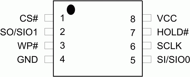
8 Pin WSON8 - Pro & Slim
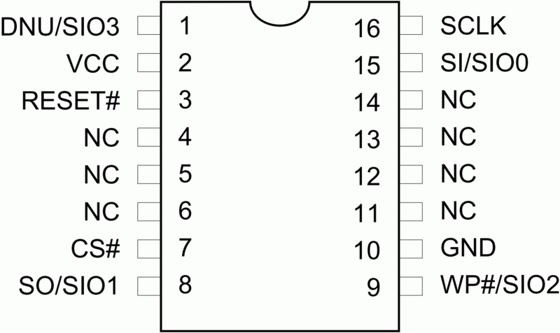
16 Pin SOP16 - Fat

Hardwiring Example

Non-Invasive Method

2.8v CH341A Mod
- Run BwE PS4 NOR Validator
- Select NOR
- Patch and Swap CoreOS
- Enable UART Mode
 DARKNESMONK
PDJ
Hoea
Donators & Suppliers of Dumps/Syscons