Kicad files for the Fan-Tas-Tic pinball controller. No tiny SMD components, can be easily assembled by hand. Designed for the milling machine (2 sided but no real vias, using through hole components instead).
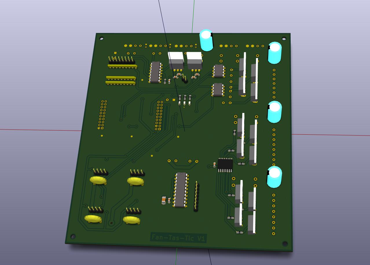
- Based on TM4C123GXL evaluation board
- 8 x 8 Switch matrix inputs (Operating on 12 V)
- 12 x on-board open drain drivers for solenoids
- 4 of them can do hardware PWM (> 100 kHz)
- Fused in groups of 4
- 4 x I2C channels for hardware extension boards. In- / Outputs can be easily and cheaply added with PCF8574 I2C GPIO extenders
- 3 x SPI channels for running WS2811 / WS2812 LED strings. Up to 1024 LEDs / channel.
- USB virtual serial connection to host PC (or Raspberry PI)
- 5 V can come from USB or from external 24 V input (Set JP1)
- SMD resistors / capacitors = 0805
- Switch matrix driver: TPIC6B595 (eBay)
- GPIO extender: PCF8574 (eBay)
- Dual power mosfet driver: UCC27524
- Power mosfets: IRL640
- Signal mosfet for I2C level conversion: BSS138
- 8 pin solenoid and 4 pin power connectors: HT396
- 8 pin switch-matrix and 4 pin I2C connectors: KF2510
The current version of the Mainboard PCB (06/2016) has been tested and worked as expected without any major problems. See also the development blog. For the next revision, these (minor) issues will be fixed:
DebugUSB connector on the Tiva board interferes with the I2C connectors on the mainboard. These will be moved.- An
InterlockRelay will be introduced on the 24 V supply line for the solenoid drivers. This is needed as the I2C port extenders have by default all outputs active before beeing initialized (which only happens a few 10 ms after power up). Furthermore, if the firmware crashes, has I2C connection issues or locks up, it can cut the power from an fault-handler. - Freewheeling diodes MUST be Schottky diodes and will be included on the PCB next to the mosfets (not on the solenoids!) for accetable EMI performance. This has been found experimentally (http://yetifrisstlama.blogspot.fr/).
- More footprints for decoupling caps will be included
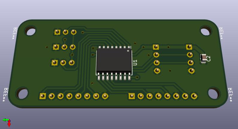
- 8 shiny new input channels for your pinball machine
- as simple and cheap as it gets
- read out a zooming 1000 times a second
Built, tested, works as expected :)
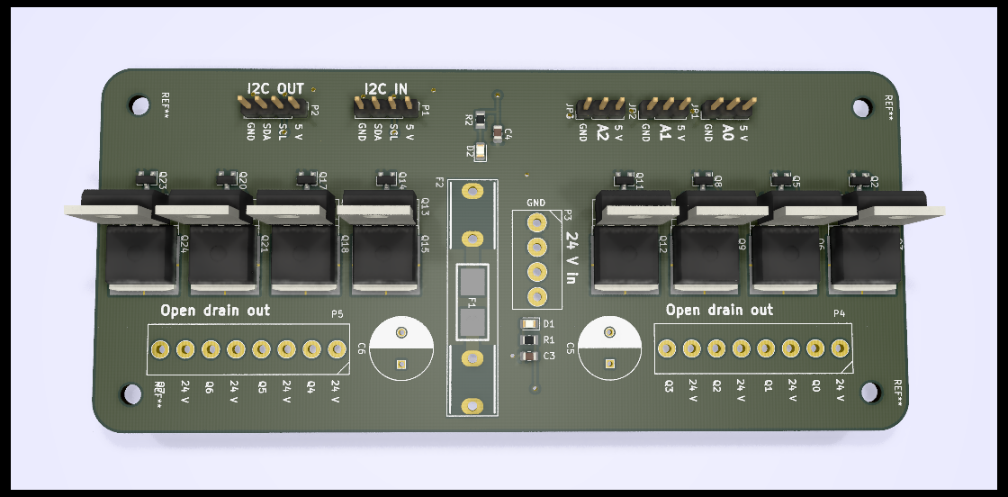
- 8 beefy open drain outputs to rock some solenoids
- BYOM! Bring your own mosfets ... supports TO-220, TO-263 and SOT23 footprints
- Fused, to keep the magic smoke in
- Also drives motors, LED strings, LED floodlights ...
Built, tested, no issues found. Drives my score reels like a charm.