Placement file issue reported by JLCPB #3
Comments
|
Original Placement: |
|
I will update you once it arrive and I have chance to test it. |
|
This is exactly what happened with my order but I verified their correction
and it seemed ok and when the boards worked with no problem.
I presume that they use the footprints from Easy EDA where they have
different center and orientation then the Kicad footprints I used.
…On Mon, Jul 26, 2021 at 6:46 AM coelholm ***@***.***> wrote:
I will update you once it arrive and I have chance to test it.
—
You are receiving this because you are subscribed to this thread.
Reply to this email directly, view it on GitHub
<#3 (comment)>,
or unsubscribe
<https://github.com/notifications/unsubscribe-auth/AAQVMQLAQWYR3D57ZWMFXPDTZVRNDANCNFSM5BADO6NQ>
.
|
|
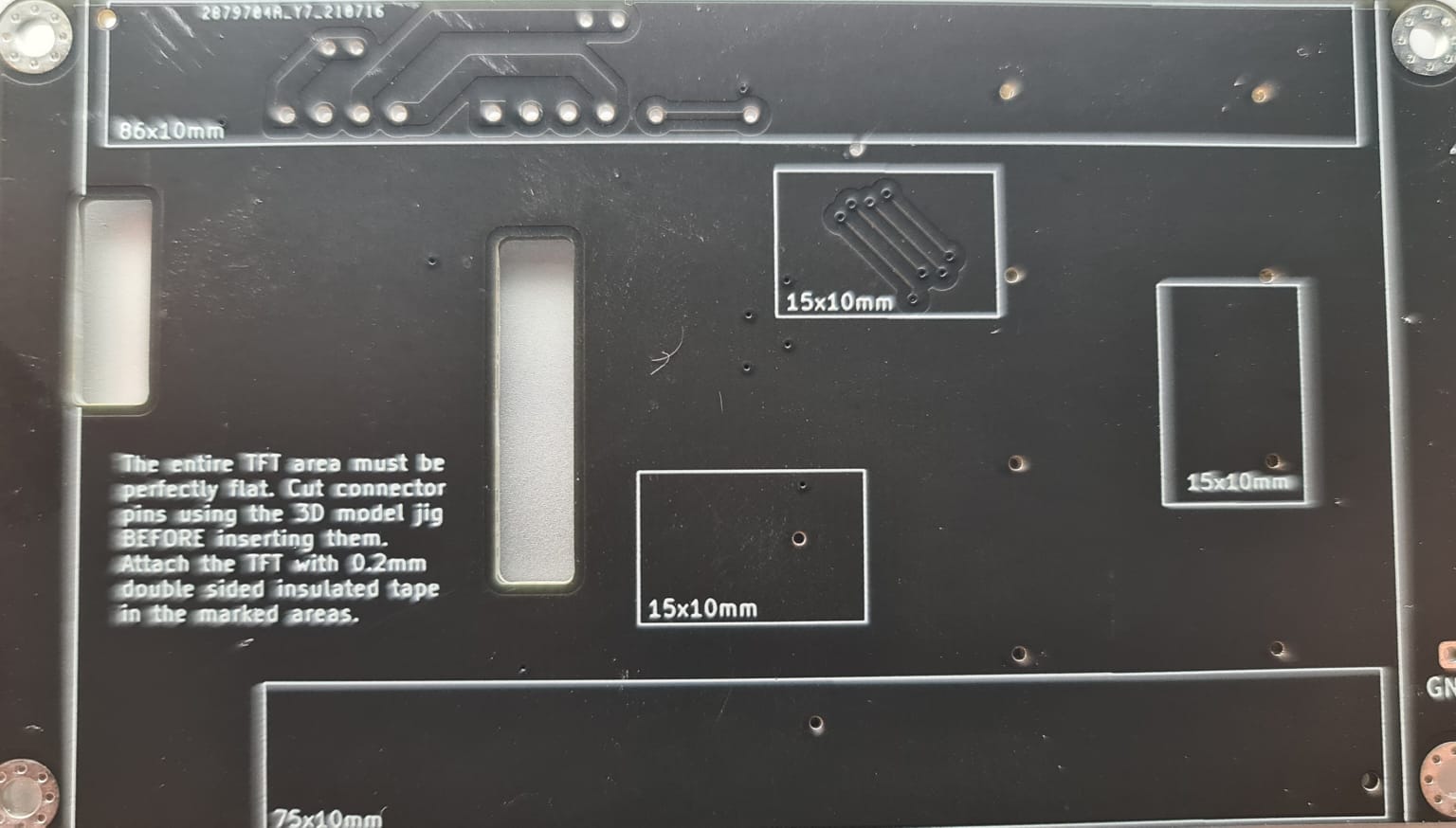
BTW, two assembly hints:
1. I recommend this 10mm double side tape. I use it for the Pico, avoid it
touching the main PCB, and for the TFT. Available also from Aliexpress and
other sites.
https://www.amazon.com/gp/product/B072JJD2ND
2. Check the 3D directory for the STL file of the 3D printed connector jig.
I use it to cut the stepper connectors pins to the right side, keeping the
TFT side of the PCB flat.
3. I recently added a 3D model for an enclosure that doesn't need heat set
threaded inserts. Easier to build and good enough.
4. For firmware binary I recommend using the one from the latest firmware
release. (unless you want to modify and compile yourself).
Please let me know if you encounter any issues.
…On Mon, Jul 26, 2021 at 10:09 AM Tal Dayan ***@***.***> wrote:
This is exactly what happened with my order but I verified their
correction and it seemed ok and when the boards worked with no problem.
I presume that they use the footprints from Easy EDA where they have
different center and orientation then the Kicad footprints I used.
On Mon, Jul 26, 2021 at 6:46 AM coelholm ***@***.***> wrote:
> I will update you once it arrive and I have chance to test it.
>
> —
> You are receiving this because you are subscribed to this thread.
> Reply to this email directly, view it on GitHub
> <#3 (comment)>,
> or unsubscribe
> <https://github.com/notifications/unsubscribe-auth/AAQVMQLAQWYR3D57ZWMFXPDTZVRNDANCNFSM5BADO6NQ>
> .
>
|
|
Thank you for those hints. I've order that tape and for sure that guide will help to cut connector. |
|
Please see if you can get from JLCPCB the corrected placement file and then
send me a pull request so others will not have to go through this confusion.
…On Thu, Jul 29, 2021 at 9:48 AM coelholm ***@***.***> wrote:
Thank you for those hints. I've order that tape and for sure that guide
will help to cut connector.
—
You are receiving this because you commented.
Reply to this email directly, view it on GitHub
<#3 (comment)>,
or unsubscribe
<https://github.com/notifications/unsubscribe-auth/AAQVMQKI4HH7XSRUARKTB73T2GA55ANCNFSM5BADO6NQ>
.
|
|
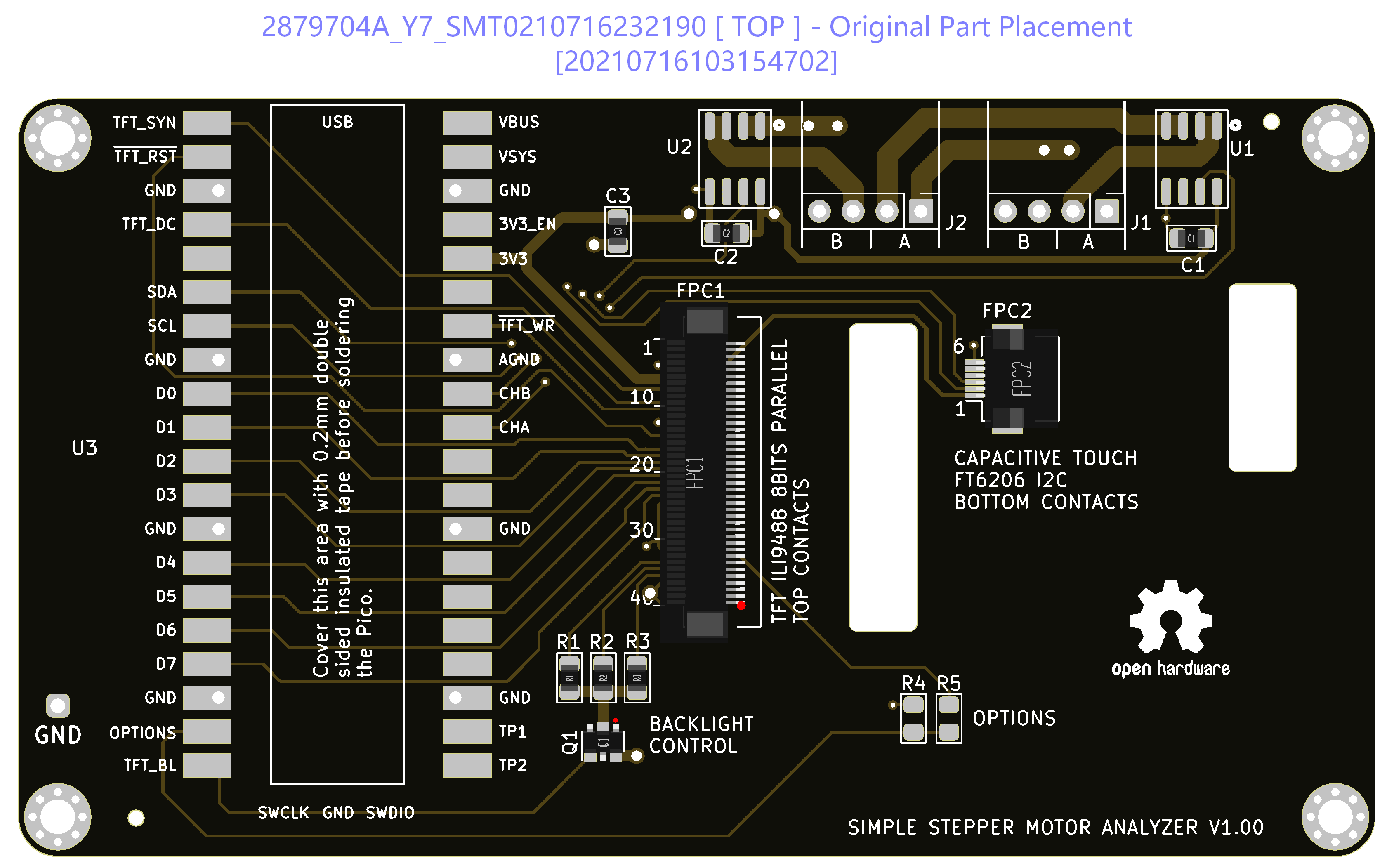
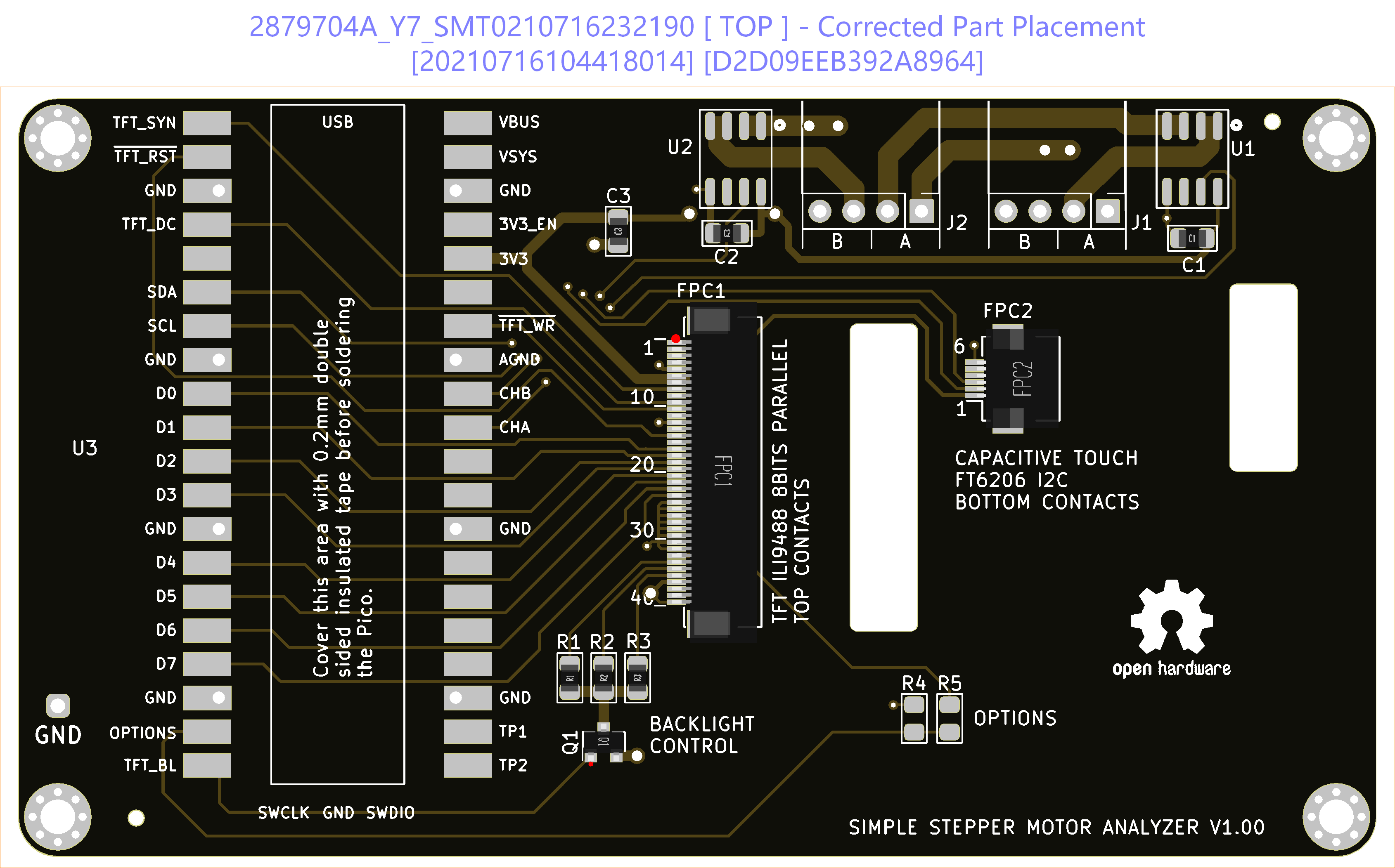
I've just tried with JLCPCB support to get that file without success. They said it is not possible to generate or provide details of adjusts made in their internal system, so I decided to spend some time trying to figure out by my self. Looks like issue was related to FPC1 (Position and rotation: 51.3,28.86,-90 ) and Q1 (Rotation only: -90) ` C1,100nf,SMD 0805,87.16,46.468,0,top |
|
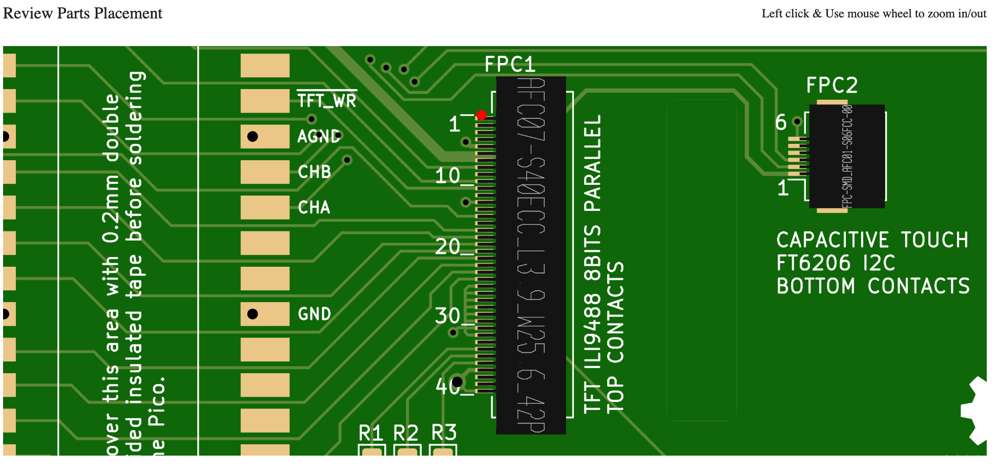
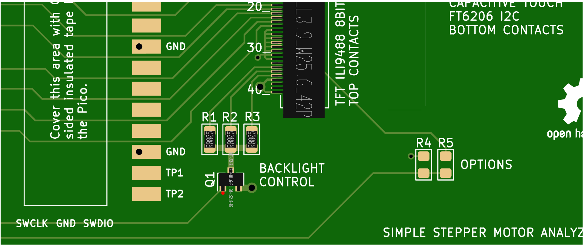
Those screenshots are from JLCPCB "Review Parts Placement" tool. FPC1 Q1 |
|
Hi @zapta Hope you can help me with that. Finally I have all parts, PCB and time to assembly it (at least I thought I had all parts) . LCD and CPT came from the store listed in the BOM.xlsx, but looks like I got the wrong one, with controller R61529 instead of ILI9488. Serial output: 0 0 0 0 0 0 0 0 0 0 0 0 0 0 0 0 0 0 0 0 Free memory: 49127 total_size=32768, free_cnt=3, free_size=7128, free_bigest_size=6988 0 0 0 0 0 0 0 0 0 0 0 0 0 0 0 0 0 0 0 0 Free memory: 49127 total_size=32768, free_cnt=3, free_size=7128, free_bigest_size=6988 |
|
Hi @coelholm,
1. Can you post a picture of your board, front and back.
2. What TFT are you using? (link to source)
3. The pins of the FPC connectors bridge easily from soldering. Can you
test for shorts among adjacent pins that are not shorted in the schematic.
4. Do you happen to have an oscilloscope?
…On Tue, Aug 24, 2021 at 8:35 PM coelholm ***@***.***> wrote:
Finally I have all parts, PCB and the time to assembly it.
I have assembled everything and update the firmware.
The LCD backlight is on, but it blank. From serial I can see some
messages, but I can't figure out what might be going on.
dfsdfsf
`0 0 0 0 0 0 0 0 0 0 0 0 0 0 0 0 0 0 0 0
0 0 0 0 0 0 0 0 0 0 0 0 0 0 0 0 0 0 0 0
[1500160][er:0, 0] [ -9, -25] [en:0 0] s:2/0 steps:0 max_steps:0
DMA counters: 4394, 4394, 0
Free memory: 49127
Options: [DEFAULT]
Pico SDK version: 1.1.2.WizIO
total_size=32768, free_cnt=3, free_size=7128, free_bigest_size=6988
used_cnt=818, max_used=26124, used_pct=79, frag_pct=2
0 0 0 0 0 0 0 0 0 0 0 0 0 0 0 0 0 0 0 0
0 0 0 0 0 0 0 0 0 0 0 0 0 0 0 0 0 0 0 0
[1500160][er:0, 0] [ -12, -26] [en:0 0] s:2/0 steps:0 max_steps:0
DMA counters: 5860, 5859, 0
Free memory: 49127
Options: [DEFAULT]
Pico SDK version: 1.1.2.WizIO
total_size=32768, free_cnt=3, free_size=7128, free_bigest_size=6988
used_cnt=818, max_used=26124, used_pct=79, frag_pct=2`
—
You are receiving this because you commented.
Reply to this email directly, view it on GitHub
<#3 (comment)>,
or unsubscribe
<https://github.com/notifications/unsubscribe-auth/AAQVMQJAMXP6UCYH34EGVQDT6RQG3ANCNFSM5BADO6NQ>
.
Triage notifications on the go with GitHub Mobile for iOS
<https://apps.apple.com/app/apple-store/id1477376905?ct=notification-email&mt=8&pt=524675>
or Android
<https://play.google.com/store/apps/details?id=com.github.android&utm_campaign=notification-email>
.
|
|
Hi @zapta , Thank you for your help. Front Back
|
.jpeg)
|
Hi @coelholm, the assembly of the PCB looks right to me. Are you sure that
your TFT panel has the ILI9488 controller? The title and the description
on Aliexpress mention R61529 which is a different controller.
This is how my TFT looks like https://i.imgur.com/IsJELb1.png . It's the
"3.5 LCD CTP" option here https://www.aliexpress.com/item/32862869103.html
…On Thu, Aug 26, 2021 at 7:16 PM coelholm ***@***.***> wrote:
Hi @zapta <https://github.com/zapta> ,
Thank you for you help.
1.
Front
[image: JLCPCB front]
<https://raw.githubusercontent.com/coelholm/simple_stepper_motor_analyzer/main/www/WhatsApp%20Image%202021-08-26%20at%2022.58.19(1).jpeg>
Back
[image: JLCPCB back]
<https://raw.githubusercontent.com/coelholm/simple_stepper_motor_analyzer/main/www/WhatsApp%20Image%202021-08-26%20at%2022.58.19.jpeg>
1.
Aliexpress TFT Last item: LCD and CPT
<https://www.aliexpress.com/item/32376432904.html?spm=a2g0s.9042311.0.0.27424c4duNePws>
2.
I have checked that visually, tested from Raspberry pins to the FPC
connectors and I didn't notice any bridge. I have also assembled to boards.
3.
I have an oscilloscope, just let me know what you need. It is a new
tool for me, but I have a good friend to ask some help if I can't follow
what you want me to do.
—
You are receiving this because you were mentioned.
Reply to this email directly, view it on GitHub
<#3 (comment)>,
or unsubscribe
<https://github.com/notifications/unsubscribe-auth/AAQVMQJXF4MEROTJABTV52TT63YPBANCNFSM5BADO6NQ>
.
Triage notifications on the go with GitHub Mobile for iOS
<https://apps.apple.com/app/apple-store/id1477376905?ct=notification-email&mt=8&pt=524675>
or Android
<https://play.google.com/store/apps/details?id=com.github.android&referrer=utm_campaign%3Dnotification-email%26utm_medium%3Demail%26utm_source%3Dgithub>.
|
|
@zapta , It is the r61529, my mistake. I have mentioned that. I have found a reference code for r61529 and arduino, but looking into display code for ili9488 I found some assembly code. So I have no idea on how to evaluate the effort of adding support for the r61529. |
|
Hi @coelholm, I don't expect the current firmware to support r61529.
Can you get the LCD from the link I posted?
…On Fri, Aug 27, 2021 at 2:06 PM coelholm ***@***.***> wrote:
@zapta <https://github.com/zapta> ,
It is the r61529, my mistake. I have mentioned that.
—
You are receiving this because you were mentioned.
Reply to this email directly, view it on GitHub
<#3 (comment)>,
or unsubscribe
<https://github.com/notifications/unsubscribe-auth/AAQVMQLRZRK3AS5AXJ7MQNLT6745JANCNFSM5BADO6NQ>
.
Triage notifications on the go with GitHub Mobile for iOS
<https://apps.apple.com/app/apple-store/id1477376905?ct=notification-email&mt=8&pt=524675>
or Android
<https://play.google.com/store/apps/details?id=com.github.android&referrer=utm_campaign%3Dnotification-email%26utm_medium%3Demail%26utm_source%3Dgithub>.
|
|
Hi @zapta, I have ordered from the link you posted. So it should solve the problem. I appreciate your support. Thank you so much. Just as a reference this is a basic example with initialization sequence for the R61529. ESP32_LCD_MIPI_DBI_TYPE_B_TEST |
|
Thanks coelholm.
I have a r61529 display and planned to write a driver for it but am busy
and can't see how I will get to it any time soon.
The plan was to have an alternative code for this ili9488 driver
https://github.com/zapta/simple_stepper_motor_analyzer/blob/main/platformio/src/display/tft_driver.cpp#L334.
Need also to see if the pinout is compatible and if the firmware can read
and detect which TFT is in use. Otherwise, it can be set during
assembly using the reserved 'options' jumper footprints on the PCB.
Anyway, please let me know if you will encounter any problem with the new
displays.
…On Fri, Aug 27, 2021 at 4:20 PM coelholm ***@***.***> wrote:
Closed #3
<#3>.
—
You are receiving this because you were mentioned.
Reply to this email directly, view it on GitHub
<#3 (comment)>,
or unsubscribe
<https://github.com/notifications/unsubscribe-auth/AAQVMQK55DPNCGSVKLWL6A3T7AMTRANCNFSM5BADO6NQ>
.
Triage notifications on the go with GitHub Mobile for iOS
<https://apps.apple.com/app/apple-store/id1477376905?ct=notification-email&mt=8&pt=524675>
or Android
<https://play.google.com/store/apps/details?id=com.github.android&referrer=utm_campaign%3Dnotification-email%26utm_medium%3Demail%26utm_source%3Dgithub>.
|
I have ordered the PCB from JLCPCB using production files from https://github.com/zapta/simple_stepper_motor_analyzer/tree/main/kicad/JLCPCB
They found placement minor issues with FPC1 and FPC2. From pictures looks like FPC1 is flipped horizontally, but I couldn't figure out any correction of FPC2.
It was corrected by JLCPCB before production, but I would like to let you know.
The text was updated successfully, but these errors were encountered: