Contents:
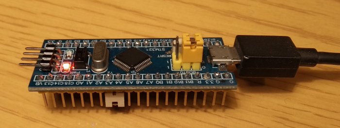
Universal RC Joystick (URCJ) is a firmware for the popular STM32F103 board (aka blue pill) which allows you to use a RC receiver with any device/software that supports USB HID Joystick.
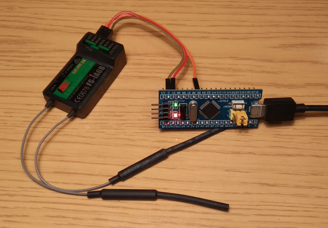
Your transmitter sends wirelessly the signal to the receiver, the receiver passes it to the STM32 board, which presents the data to the host device as a standard USB HID Joystick.
- A STM32F103 Blue pill board. Clones can be found for very cheap ($2-$3 at AliExpress for example). The STM32F103C6T6 (note the C6) is cheaper and also works.
- A micro USB cable
- ST-Link or UART converter for flashing (see below).
- A RC receiver
The following protocols are currently supported:
Digital:
- SBUS (inverted and uninverted) – FrSky, Futaba and others
- IBUS – FlySky (iA6 is also supported. See here for how to get the digital signal)
- DSM – Spektrum
- FPort (inverted and uninverted) – FrSky
Analog:
- PPM – vendor independent. Note that digital protocol is always preferable because of its much lower latency
First head over to the releases section and download the appropriate .hex file depending on whether you have the C6 or C8 board.
Using ST-Link is the standard way for flashing STM32 chips. There are many tutorials that explain how to do it (like this).
Most people don't really need to flash STM32 chips in their day to day life so buying a ST-Link to use it only once is really an overkill. STM32 chips can also be programmed through UART serial interface. It's much more likely that you already have such a converter, such as FTDI adapter. There are many options.
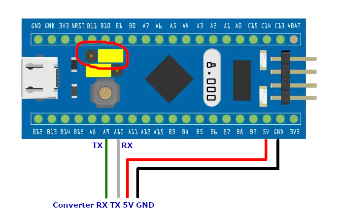
- You'll need to move the
BOOT0jumper to the1position - Connect the
A9pin (the STM32 sends data out through that pin) to theRXpin of the converter - Connect the
A10pin (the STM32 receives data through that pin) to theTXpin of the converter - Connect
GND - Connect
5V
If you don't have a UART converted but you have an Arduino board, you can use that too because it comes with UART converter. But there are few things to take into account:
!!! Please read and understand the points below, otherwise you may damage your devices!
- Flash an empty sketch to the Arduino first! This is needed to make sure that all pins are in their default input state (high impedance). If some of the pins are set to outputs you may burn something (if two pins which are connected together, output
0and1respectively, they are practically shorted!). We need the Arduino board only for its UART converter. - You need to connect in the following way:
| STM32 | Arduino |
|---|---|
| A9 (TX) | TX |
| A10 (RX) | RX |
It may seem strange that we connect TX to TX and RX to RX. The reason is because the labels on the Arduino board are from the standpoint of the Atmega chip. The TX pin is internally connected to the RX pin of the UART chip (and that's where we want to hook the STM32's TX).
Assuming that your UART converter is connected, there are few ways in which you can do the actual flashing.
- Use a tool like stm32loader. You can see a guide here
- But there's easier way if you already have the Betaflight configurator installed.
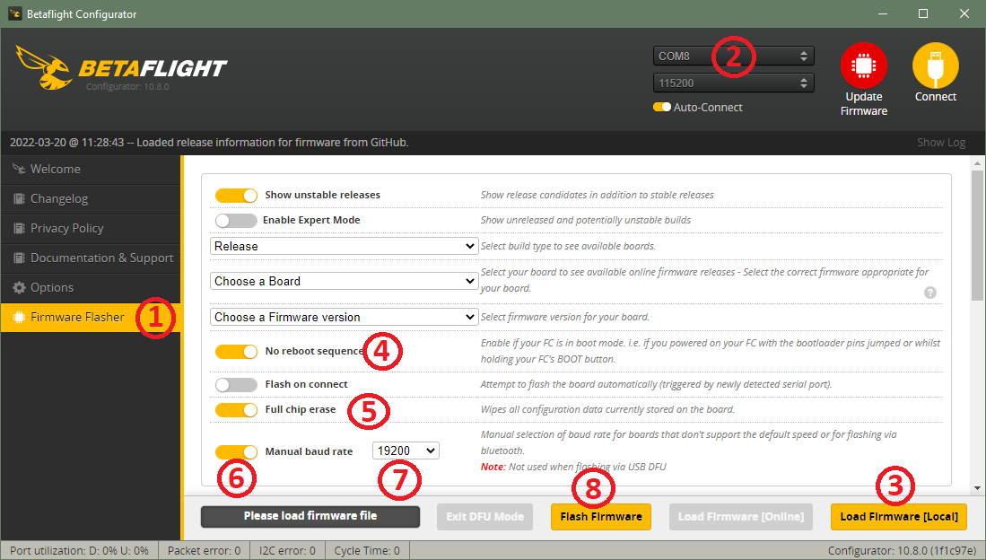
- Go to the
Firmware Flashertab - Select the COM port of your UART converter
- Load the
.hexfile No reboot sequenceshould be checked- It's recommended that
Full chip eraseis checked - Check
Manual baud rate - This is not strictly necessary but I found out that flashing works more reliably at
19200bps - Flash. If it doesn't work try resetting the STM32 board with its
RESETbutton and try again
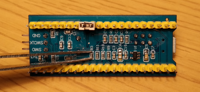
Note! There are some buggy clones which have faulty
BOOT0pin. To check if that is the case, make sure your board is powered andBOOT0is in the1position then turn the board around and measure the voltage across theR3resistor. Normally it should read 0V. If you see something like 2.3V you have one from the faulty batch.Don't worry you can still flash but you'll need some manual work. Take a pair of tweezers or something else with which you can conveniently short the resistor (make sure your tweezers are conductive - verify that there's continuity between the tips of the tweezers with your multimeter). Hold the board with one hand and prepare a finger on the
RESETbutton. With your other hand short the resistor and then press theRESETbutton. After that you can remove the shorting. The chip should now be in bootloader mode and you can perform the flashing procedure.
After you're done return BOOT0 to its original 0 position.
After the firmware has been flashed you need to connect your receiver:
| Receiver | STM32 |
|---|---|
| +5V | 5V |
| GND | GND |
| DATA | B5 |
Note that if you're using DSM receiver you should use 3.3V instead of 5V. Also the receiver should be already bound to the transmitter.
You can solder or use a jumper:
The firmware uses the standard ST provided hardware ids - VID 0483 PID 5710. It should immediately be recognized as standard USB Input Device. It should also be visible in the Game Controllers settings:
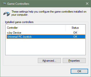
Note: since we use the standard hardware ids it's possible that other devices using the same ids have been connected to your PC at some prior point. If this is the case you may see different name for the Joystick (for example
FrSky Taranis Joystick, which uses the same standard ids). Don't worry about this.
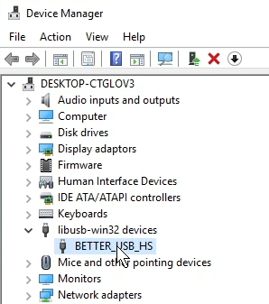
Note: some of the latest Windows 10 updates seem to automatically install another driver for these hardware ids (which unfortunately doesn't work):
If your situation is like this, please follow this guide.
URCJ is a zero-configuration tool. The type of the receiver is automatically detected. There are two modes of the LED:
| LED | Meaning |
|---|---|
| Blinking | No connection with the receiver |
| Continuous | The receiver is recognized and connected |
It is recommended that you create a separate model in your transmitter for use with URCJ. Consult your transmitter's documentation on how to do this. Make sure all controls that you need are assigned to RC channels.
The RC channels are mapped to joystick axes/buttons in the following way:
| RC Channel | USB Joystick Axis/Button |
|---|---|
| 1 | X |
| 2 | Y |
| 3 | Z |
| 4 | Rx |
| 5 | Ry |
| 6 | Rz |
| 7 | Button 1 |
| 8 | Button 2 |
| 9 | Button 3 |
| 10 | Button 4 |
Open https://gamepad-tester.com/ with a recent browser. You should be seeing your joystick there. When you move your sticks you should be seeing the raw values of the axes ranging between -1 to 1 with 0 at the center. Adjust your endpoints and center (sometimes called subtrim) if needed.
Buttons are considered to be pressed when the channel's value is above halfway (> 1500)
At this point everything should be working and you are ready to use URCJ with your favorite sims. Note that even though the examples above are for Windows, URCJ should work on any platform (Mac, Linux, Android, etc.) as long as it supports USB HID devices.
The skeleton of the firmware is generated with STM32CubeMX (project file is urcjoy.ioc). Development is done in Visual Studio Code together with the PlatformIO extension.
Turning the STM32 board into a USB HID device is standard code. Reading the receiver is also straightforward. The only difficulty is that the SBUS protocol uses inversed polarity of the UART signal. Unfortunately the F103 series does not support software inversion of the signal. The employed solution is the following:
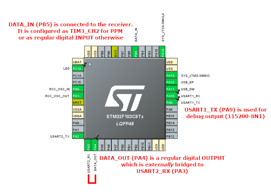
There are two different modes of operation:
-
PPM. In this mode
DATA_INis configured as Timer3 Channel2 and used to capture the length of the PPM pulses. -
Digital protocols. Here
DATA_INis a regular GPIO Input. Any changes to that pin are caught by the interrupt handler. Then the state is immediately written toDATA_OUTbut we have two cases:a. Inverted signal - we write to
DATA_OUTthe inverted value (that is, ifDATA_INis0we write1toDATA_OUTand vice versab. Normal signal - we write the same value to
DATA_OUT
Then the externally bridged signal is read by USART2.
Once the RC data is decoded it is sent over USB.
If this software brought a smile on your face, you may shine back if you feel like it:
Thank you!!!
